
Cooking tray for rapid cook oven

a technology for rapid cooking and ovens, applied in ovens, electric/magnetic/electromagnetic heating, electrical appliances, etc., can solve the problems of affecting the performance of the rapid cook oven, correspondingly more difficult to provide a cooking tray suitable for use therewith, and difficult to move foodstuffs directly into or out of the hot oven without the use of a cooking tray

Inactive Publication Date: 2005-07-07
TURBOCHEF TECH INC
View PDF18 Cites 16 Cited by
  • Summary
  • Abstract
  • Description
  • Claims
  • Application Information

AI Technical Summary

Problems solved by technology

In a commercial environment such as a busy restaurant, moving foodstuffs directly into or out of hot oven without the use of a cooking tray may be difficult, messy, time-consuming and hazardous.
As cooking ovens have become more complex and sophisticated, it has become correspondingly more difficult to provide a cooking tray suitable for use therewith.
In a rapid cook oven, however, the type of cooking tray can greatly impact the performance of the rapid cook oven, frequently requiring significantly longer cook times. For example, in a microwave oven a metallic sheet pan will block microwave energy from entering the foodstuff from the side in contact with the metallic pan.
Further, in a convection oven, the use of a metallic or ceramic cooking tray may strongly impact the degree of browning obtainable due to the time it takes to heat the tray to a browning temperature.
However, in rapid cook ovens where the total cook time may be only 35 to 120 seconds, the time required to heat the cooking tray may represent a significant fraction of the total cook time, thereby requiring a longer total cook time.
Thus each of the heat transfer mechanisms used by a particular rapid cook oven imposes requirements on the cooking tray and limits those trays which are suitable for use in that particular oven.

Method used


Image

  • Cooking tray for rapid cook oven
  • Cooking tray for rapid cook oven

Examples


Embodiment Construction

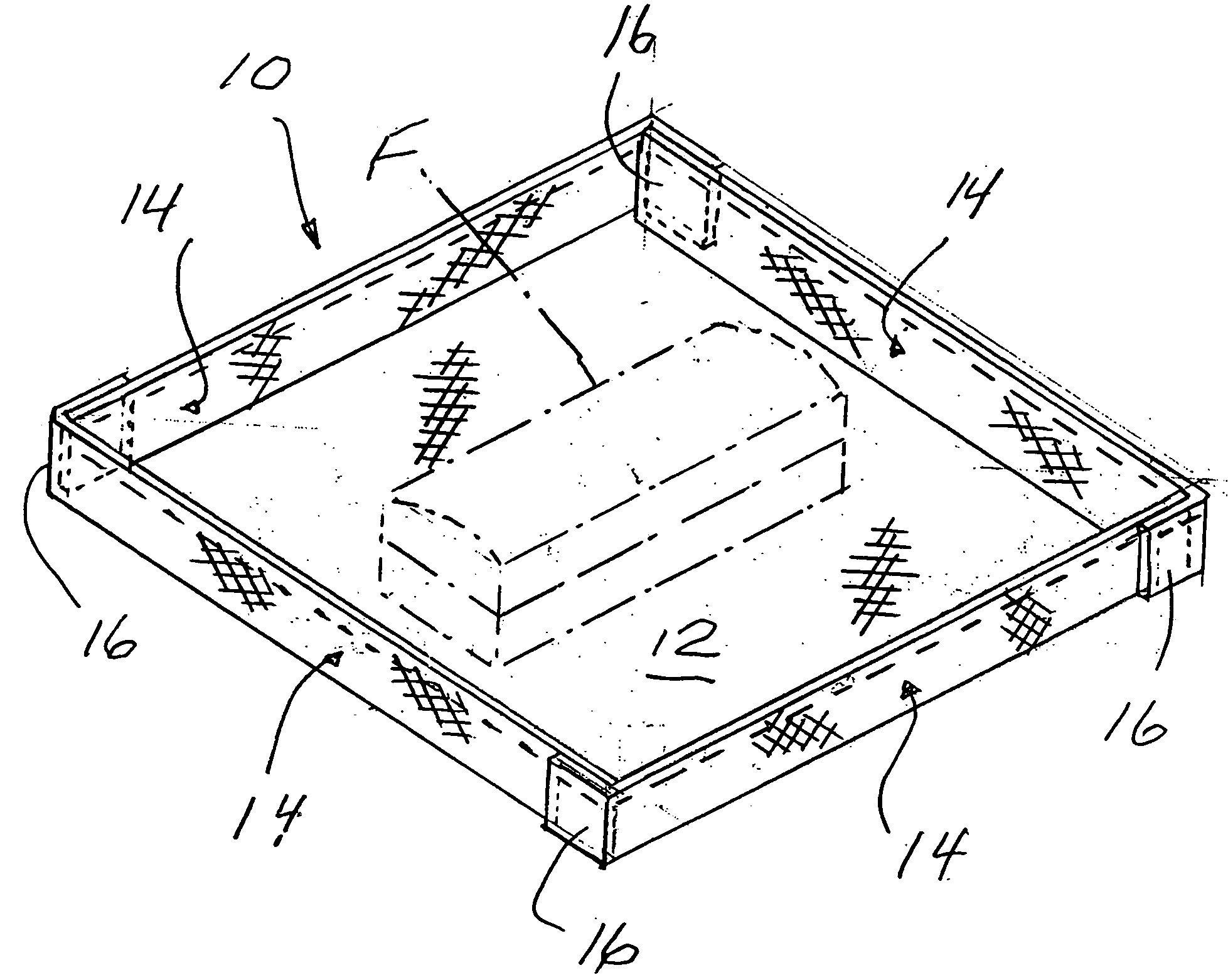
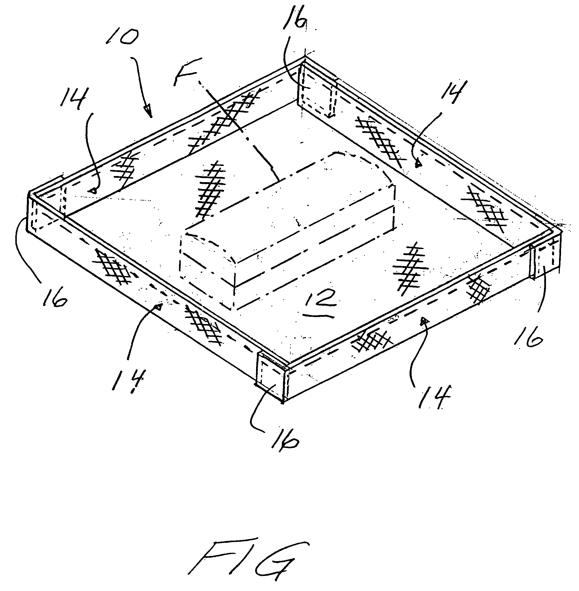
[0020] Referring now to the drawing, and in particular to the FIGURE thereof, therein illustrated is a cooking tray according to the present invention, generally designated by the reference numeral 10. The tray 10 defines a base, generally designated 12, and an upstanding peripheral sidewall, generally designated 14, extending completely about the base 12. The base 12 and sidewall 14 cooperatively define an open-top container for the collection of solid debris created during cooking.

[0021] The tray 10 may be formed of a woven material defining interstices or a nonwoven material. Where the material is a nonwoven material for use in a convection oven, it is preferably perforated or apertured to define interstices, at least in the base 12 thereof, to allow hot air flow therethrough. The term “interstices” as used herein includes small apertures and perforations sufficient to allow airflow therethrough, but not solid food particles. A preferred construction is of fiberglass material ha...


PUM


Abstract

A cooking tray (optionally interstices-defining, microwave-transparent and providing an appropriate view factor) has a one-piece, integral, unitary construction formed of a food-grade, non-stick material suitable for use in a rapid cook oven which cooks by a combination of at least two heat transfer mechanisms selected from the group consisting of radiant heat transfer, convection heat transfer and microwave energy transfer. The construction defines a base and an upstanding peripheral sidewall about the base for the collection of solid debris created during cooking. Preferably the material is food-grade fiberglass with a non-stick coating.

Description

BACKGROUND OF THE INVENTION [0001] The present invention relates to a cooking tray for the support of foodstuffs in an oven and the transportation thereof to and from the oven, and more particularly to such a tray which is suitable for use in a rapid cook oven. [0002] In a commercial environment such as a busy restaurant, moving foodstuffs directly into or out of hot oven without the use of a cooking tray may be difficult, messy, time-consuming and hazardous. [0003] As cooking ovens have become more complex and sophisticated, it has become correspondingly more difficult to provide a cooking tray suitable for use therewith. The cooking tray must not only support the foodstuffs within the cooking chamber of the oven, but also be suitable for the transport of the foodstuffs to and from the oven. In the past, cooking trays were simple metallic or ceramic-like vessels such as a metallic sheet pan, a ceramic bowl, a pot or the like. [0004] In a rapid cook oven, however, the type of cookin...

Claims


Application Information

Patent Timeline
IPC IPC(8): A21B3/13A21B3/15F24C15/16
CPCF24C15/16A21B3/15
Inventor POOL, JAMES K. IIIASHCRAFT, PETER
Owner TURBOCHEF TECH INC
Learn More