
Hitless variable-reflective tunable optical filter

a tunable reflection, optical filter technology, applied in the field of optical communication, can solve the problems of inadvertent blockage of channels, device spectrally selectiveness, and difficulty in achieving both of these goals

Inactive Publication Date: 2005-07-07
INTEL CORP
View PDF5 Cites 33 Cited by
  • Summary
  • Abstract
  • Description
  • Claims
  • Application Information

AI Technical Summary

Problems solved by technology

Such devices may not be spectrally selective.
When an optical filter is tuned, it may inadvertently block a channel that should not be dropped.
Accomplishing both of these goals has been challenging, at times requiring additional switches to make an OADM hitless and additional attenuators for power balancing of the added and dropped channels.

Method used


Image

  • Hitless variable-reflective tunable optical filter
  • Hitless variable-reflective tunable optical filter
  • Hitless variable-reflective tunable optical filter

Examples


Embodiment Construction

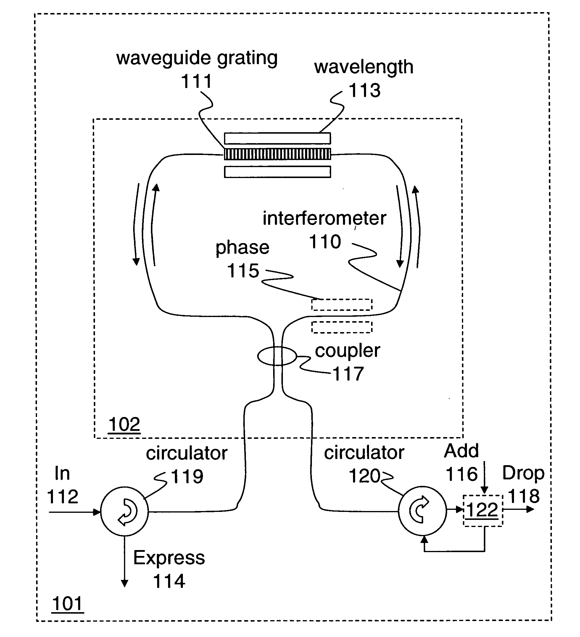
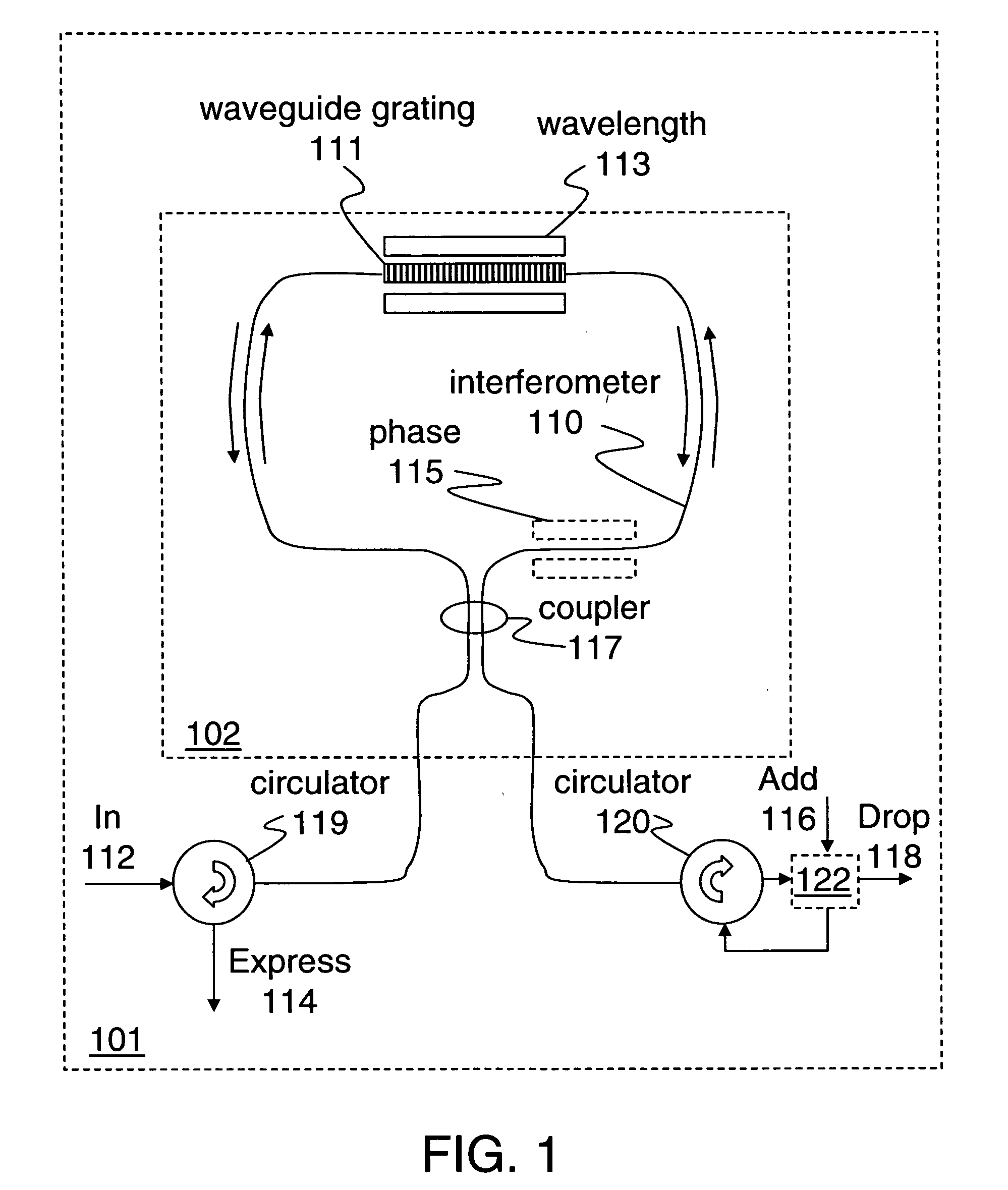
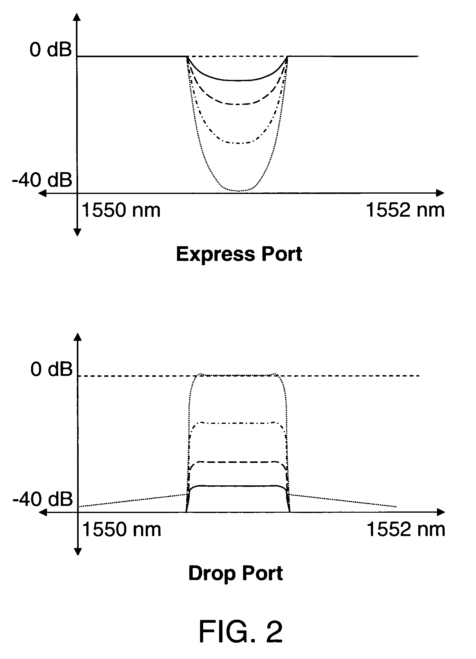
[0013] Disclosed herein are processes and apparatus for variable-reflective tunable optical filtering. One embodiment of a variable-reflective tunable optical filter includes an interferometer adapted to control the magnitudes of added or dropped signals and an optical waveguide grating to select the wavelength channels of the added or dropped signals. The waveguide grating is tunable to filter a dropped signal from an input data stream and to filter an added signal into an output data stream. While a reflection band of the waveguide grating is being adjusted to tune a wavelength channel, the phase in a leg of the interferometer may be adjusted to direct signals of any wavelength channel selected by said waveguide from the input data stream into the output data stream, thereby providing hitless optical add-drop multiplexing.

[0014] These and other embodiments of the present invention may be realized in accordance with the following teachings and it should be evident that various mod...


PUM


Abstract

A variable-reflective tunable optical filter includes an interferometer adapted to control the powers of added or dropped signals and an optical waveguide grating to select the wavelength channels of the added or dropped signals. The waveguide grating is tunable to filter a dropped signal from an input data stream and filter an added signal into an output data stream. While a reflection band of the waveguide grating is being adjusted to tune a wavelength channel, the phase of at least one leg of the interferometer may be adjusted to direct signals of any wavelength channel selected by said waveguide from the input data stream to the output data stream, thereby providing hitless optical add-drop multiplexing.

Description

FIELD OF THE DISCLOSURE [0001] This disclosure relates generally to the field of optical communications. In particular, the disclosure relates to an optical filter with a continuously variable reflectivity and tunable reflection band. BACKGROUND OF THE DISCLOSURE [0002] Tunable optical filters may be used in multi-wavelength optical communications such as wavelength-division multiplexing (WDM) systems. [0003] Currently, tunable optical filters may require a variable optical attenuator (VOA) or similar device for adjusting reflectivity. Such devices may not be spectrally selective. An arrayed waveguide grating (AWG) or similar device may be used to separate wavelength channels and an optical switching matrix may be used to add or drop selected channels. Thus the tuning and the switching in an optical filter may require a variety of these separate devices. [0004] When an optical filter is tuned, it may inadvertently block a channel that should not be dropped. In such cases, it may be ...

Claims


Application Information

Patent Timeline
IPC IPC(8): G02B6/34H04J14/02
CPCG02B6/2932G02B6/29322G02B6/29347G02B6/29383H04J14/0219H04J14/021H04J14/0212H04J14/0213H04J14/0206
Inventor GRUNNET-JEPSEN, ANDERSSWEETSER, JOHN
Owner INTEL CORP
Learn More