Door module for a vehicle
a door module and vehicle technology, applied in the field of door modules, can solve the problems of increasing the number of component parts, material costs and assembly steps, and achieve the effects of reducing the number of components, reducing the number of projections in the door panel, and simplifying the projection form
- Summary
- Abstract
- Description
- Claims
- Application Information
AI Technical Summary
Benefits of technology
Problems solved by technology
Method used
Image

Examples
first embodiment
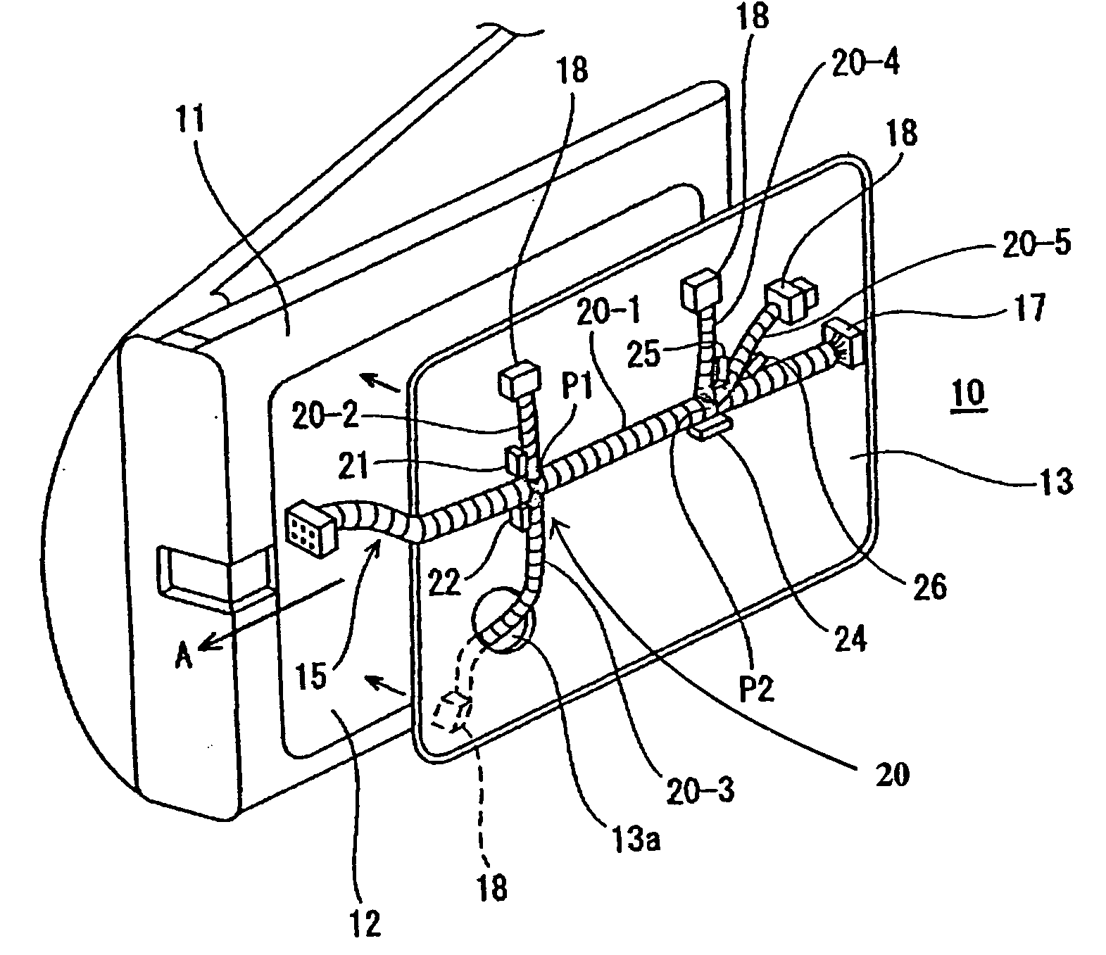
[0040] FIGS. 3 to 5 show a door module 10 according to the invention. The door module 10 includes a detachable panel 13 which may be formed of any suitable material such as, for example, a resin. The detachable door panel 13 has been previously equipped with a door harness 20-1, 20-2, 20-3, 20-4, 20-5, a window power wind motor, a motor for a remote-controlled mirror, a power wind switch and a switch for a remote-controlled mirror. A door inner panel 11 of the door module has a recessed portion 12, into which the detachable panel 13 is fitted and fixed thereto. The door harness 20-1; 20-2, 20-3, 20-4, 20-5 wired on the detachable panel 13 may include, for example, a trunk or stem wire harness 20-1 portion and branched wire harness portions 20-2, 20-3, 20-4, 20-5. An end of the trunk portion 20-1 of the wire harness is connected to another wire harness located in a body panel of a vehicle (not shown in the figure), as illustrated in FIG. 3 by the arrow A. The other end of the trunk p...
third embodiment
[0047]FIGS. 7A and 7B show the present invention, in which an L-shaped projection 31 is provided, in addition to the projections 21, 22, 23, 24, 25, 26, at a position substantially half way between the branching points P1 and P2. The other configurations are as in the previous embodiments and shown by the same references, and the descriptions are not repeated. As shown in FIGS. 7A and 7B, the L-shaped projection 31 includes a first holding portion 31a projecting perpendicularly from the door panel, and a second holding portion 31b extending from the first holding portion 31a, in a direction substantially parallel to the door panel. The internal face 31c of the first holding portion 31a flanks the trunk portion 20-1 of the wire harness from below, while the second holding portion 31b covers the trunk portion 20-1 of the wire harness. In this configuration, the L-shaped projection 31 supports the trunk portion 20-1 of the wire harness 20-1 from below, and the second holding portion 31...
fourth embodiment
[0048]FIGS. 8A and 8B show the present invention, in which three projections 21, 22, and 23 are arranged at the first branching point P1. In addition, an L-shaped projection 32 is provided on the periphery of and surrounding the first branching point P 1. The other configurations are the same as in the previous embodiments and the description is not repeated. Typically, the projections 21, 22, 23, 32, respectively, are arranged in a counter clockwise sequence around the first branching point P1, thereby surrounding both sides of the trunk portion 20-1 of the wire harness and branched wire harness portions 20-2 and 20-3. The large rectangular face 21a of projection 21 is placed in contact with branched wire harness portion 20-2 at the side of branching point P1 proximal to the body panel, and the large rectangular face 22a of projection 22 flanks the trunk portion 20-1 of the wire harness from below. Likewise, the large rectangular face 23a of projection 23 is placed in contact with ...
PUM
 Abstract
Description
Claims
Application Information
 - R&D
- Intellectual Property
- Life Sciences
- Materials
- Tech Scout
- Unparalleled Data Quality
- Higher Quality Content
- 60% Fewer Hallucinations
Browse by: Latest US Patents, China's latest patents, Technical Efficacy Thesaurus, Application Domain, Technology Topic, Popular Technical Reports.
© 2025 PatSnap. All rights reserved.Legal|Privacy policy|Modern Slavery Act Transparency Statement|Sitemap|About US| Contact US: help@patsnap.com