Eureka AIR delivers breakthrough ideas for toughest innovation challenges, trusted by R&D personnel around the world.

Suture anchoring device

Active Publication Date: 2005-07-07
ETHICON INC
View PDF7 Cites 26 Cited by
  • Summary
  • Abstract
  • Description
  • Claims
  • Application Information

AI Technical Summary

Benefits of technology

[0012] The present invention provides a suture anchoring device that is comprised in part of a first retaining member having a first surface, a second surface and a first outer edge that is connected via a coupler in a parallel, non-coplanar fashion to a second retaining member having a third surface, a fourth surface and a second outer edge. The first retaining member has an opening that extends from the first outer edge to at least

Problems solved by technology

In general, suture knot tying is cumbersome and is one of the more time-consuming steps in the suturing process of the surgical procedure.
This is especially true with regard to minimally invasive surgical procedures where the tying of surgical knots within confined spaces is extremely difficult and time consuming.
First, due to the suture manipulation required to use this retainer, a laparoscopic applicator device would be extremely difficult to produce profitably.
Furthermore, the wedging and clamping action will induce stress concentrations in the suture, which likely lead to reduced failure loads.
Not only does this device require laparoscopically guiding two strands of suture between two very small apertures, it also requires that the sutures be squeezed tightly by these teethed apertures, thereby diminishing the integrity of the suture and significantly reducing the maximum tension the suture can withstand.
This melting and bonding action will compromise the integrity of the suture and therefore, because suture strength is of utmost concern in most surgeries, this method of fixation of the retaining element to the suture is not suitable for most surgeries.
There is a possibility of improperly actuating or inadvertently releasing the snap, which could lead to an insecure fixation of the suture.
In addition, weak stress points are created where the suture is held within the clip.

Method used


Image

  • Suture anchoring device
  • Suture anchoring device
  • Suture anchoring device

Examples


Embodiment Construction

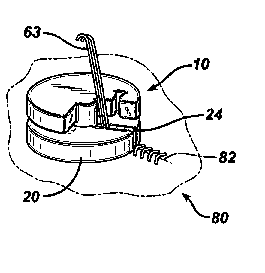
[0016] The suture anchoring device described herein can be used in combination with multiple sutures or with a single suture for various types of surgical procedures by surgeons. The suture anchoring device may be fabricated from any biocompatible medical material, such as polymeric or metallic. The polymeric material may be absorbable within a mammalian body (e.g. polydioxanone such as poly(1,4-dioxan-2-one), polymers or copolymers of organic hydroxyesters, polyglycolide, polylactide, polyhydroxy butyric acid, polycaprolactone, polytrimethylene carbonate and polyvinyl alcohol), or it may be non-absorbable (e.g. polyolefins such as polyethylene or polypropylene, polyesters, fluorpolymers such as polytetrafluoroethylene, polyamides such as nylon, and combinations thereof). Furthermore, the suture anchoring device may be fabricated via standard machining processes, injection molding, or a lithographic process (e.g. stereolithography).

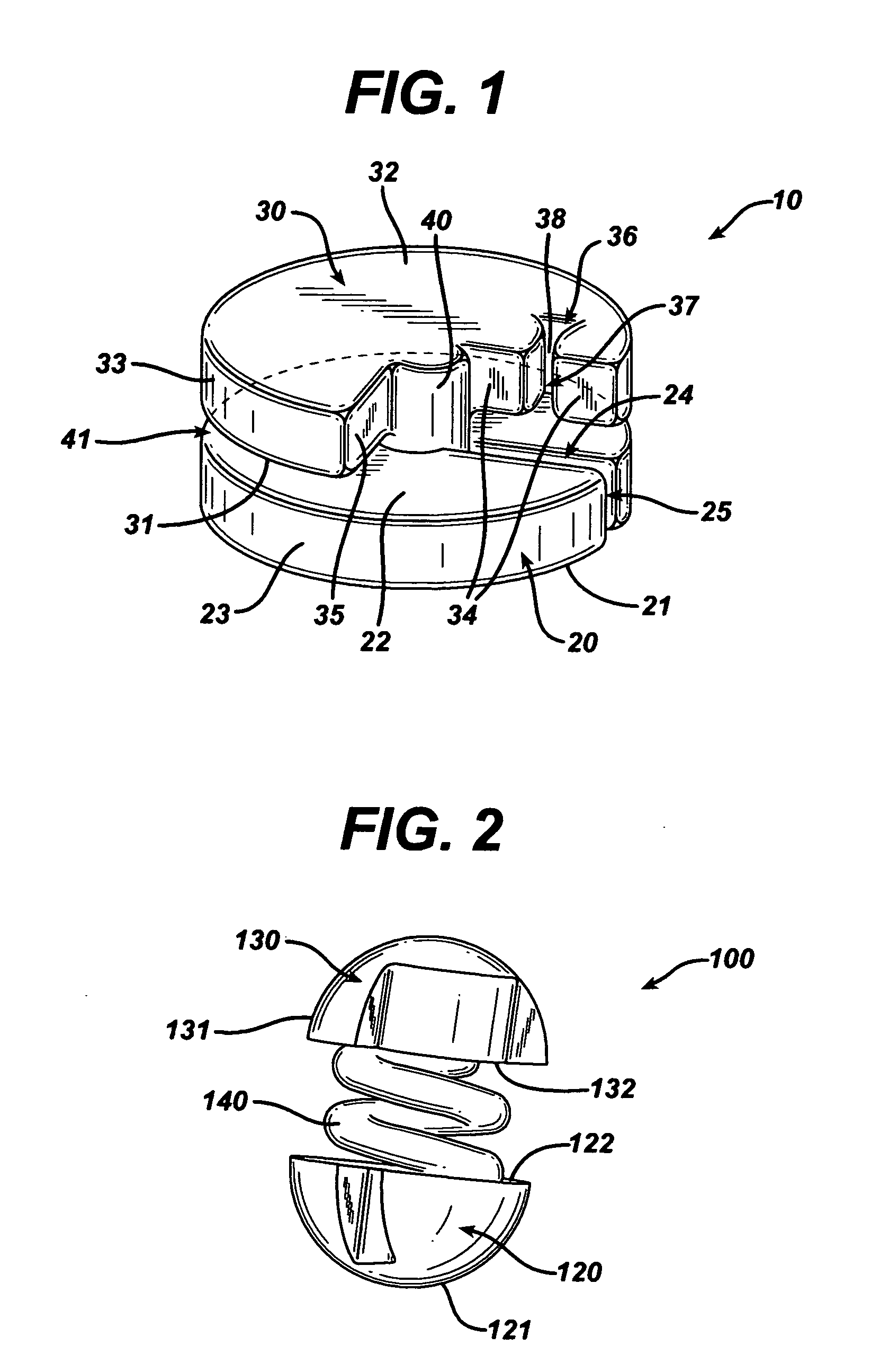
[0017] Referring to FIG. 1, there is shown a sutur...


PUM


Abstract

A suture anchoring device comprising (1) a first retaining member having a first surface, a second surface and a first outer edge; where the second surface lies in a first plane; the first retaining member having an opening that extends from the first outer edge to at least partially through the second surface to an inner point of the first retaining member; (2) a second retaining member having a third surface, a fourth surface and a second outer edge; where the third surface lies in a second plane, the second retaining member having a holding means; and (3) a coupler having a third outer edge and a cross-sectional area taken in a plane parallel to the first plane that is smaller than the cross-sectional area of the first retaining member taken in a plane parallel to the first plane; where the coupler joins the first retaining member to the second retaining member at the second surface and third surface; wherein the second and third surfaces are parallel to each other and non-coterminous.

Description

FIELD OF THE INVENTION [0001] The present invention relates to a suture anchoring and tensioning device for use with sutures in surgical procedures. More particularly, the present invention pertains to an anchoring device that maintains the tension that is set by the surgeon in at least one suture in order to anchor and restrict movement of the suture at the surgical site. BACKGROUND OF THE INVENTION [0002] In surgical procedures, sutures are commonly used to close incisions and to reunite damaged tissue. Typically, the sutures are maneuvered and passed through the affected tissue and the free ends of the sutures are individually tied together by the surgeon. In some surgical procedures, the surgical site area is sufficiently exposed to permit the surgeon to access and tie the suture manually with a surgical knot. In other surgical procedures, such as endoscopic procedures, laparoscopic procedures, arthroscopic procedures and the like, or when robotic surgical procedures occur, the ...

Claims


Application Information

Patent Timeline
IPC IPC(8): A61B17/04
CPCA61B17/0401A61B17/0487A61B2017/0404Y10T24/3998A61B2017/0496Y10T24/3918Y10T24/3916A61B2017/0454B33Y80/00
Inventor COLLIER, JOHNNERING, ROBERTNOZAD, IRENECHATLYNNE, ETAN
Owner ETHICON INC
Why Eureka
Eureka Blog
Learn More