
Intraocular lens system and method for power adjustment

Active Publication Date: 2005-07-07
ALCON INC
View PDF70 Cites 92 Cited by
  • Summary
  • Abstract
  • Description
  • Claims
  • Application Information

AI Technical Summary

Benefits of technology

[0010] In another preferred embodiment, the coincident surfaces of the first and second lens portions that bound the interior chamber are configured with projecting shape structures that cooperate with one another and fluid movement to (i) amplify the dynamic range of surface curvature modification and further (ii) to insure that the first and second lens portions are mechanically coupled to allow controlled shape change.

Problems solved by technology

Since the lens can no longer accommodate, the patient typically need glasses for reading.
In a significant number or cases, after the patient's eye has healed from the cataract surgery, there is a refractive error that could not be predicted.
There remain substantial difficulties in calculating the proper power of an IOL for any particular patient.

Method used


Image

  • Intraocular lens system and method for power adjustment
  • Intraocular lens system and method for power adjustment
  • Intraocular lens system and method for power adjustment

Examples


Embodiment Construction

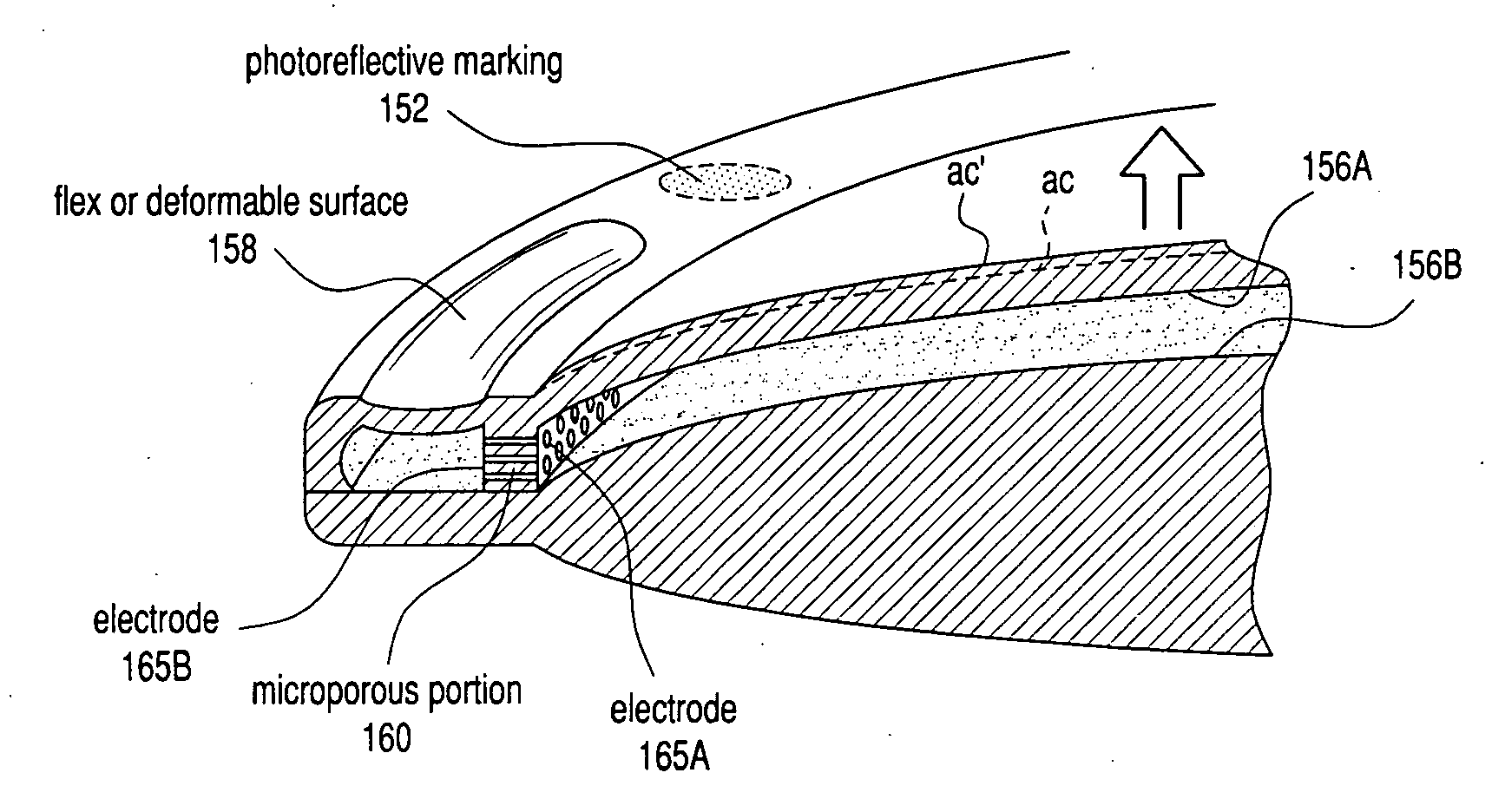
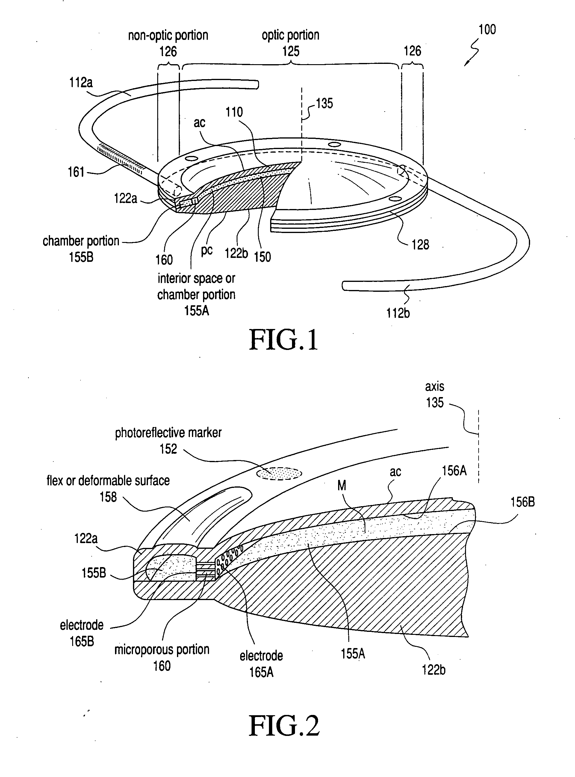
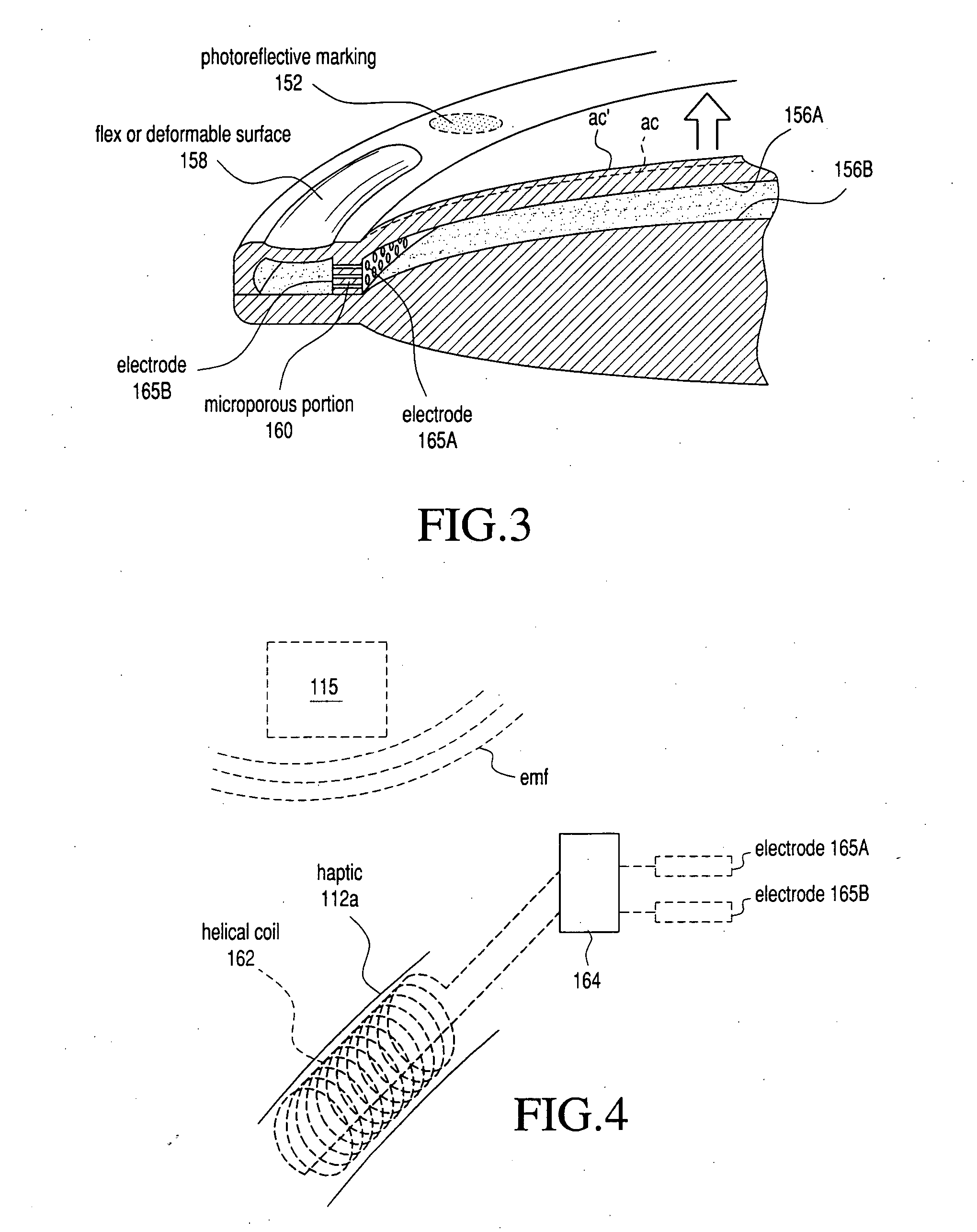
[0030] 1. Type “A” intraocular lens. FIGS. 1 and 2 illustrate an intraocular lens 100 (IOL) in accordance with the invention in which the lens body has at least one flexible or deformable surface element 110 that allows for a change in its shape or curvature to adjust the optical parameters of the lens. Deformation and shape adjustment of the surface element 110 in preferred embodiments is caused by fluid flows with an interior space of the lens to displace the surface element, when coupled with energy or stimulus from an external source 115 (see FIG. 4). In an exemplary embodiment, the IOL body 100 is coupled to a haptic portion that comprises radially-extending struts (or haptics) indicated at 112a and 112b in FIG. 1 that are coupled to the lens perimeter. Typically, the haptics 112a and 112b have radial-outward ends that define arcuate terminal portions. The haptics 112a and 112b have a particular length so that the terminal portions create a slight engagement pressure when in co...


PUM


Abstract

An intraocular lens (IOL) that provides for optical power adjustment following its implantation, for example, for use in treating cataract patients. The lens body has first and second surface portions that bound at least one interior chamber or space that extends from the central optic portion to the lens periphery. The interior chamber or space has a microporous body that is intermediate inner and outer portions of the space. In one embodiment, the microporous body is capable of cooperating with an external Rf or light source to expose a charge to a charge-carrying fluid within the interior chamber. By this system, fluid flows are induced to alter the optical parameters of the lens.

Description

CROSS-REFERENCE TO RELATED APPLICATION [0001] This application is a continuation of application Ser. No. 10 / 231,433, filed on Aug. 29, 2002, which claims benefit of U.S. Provisional Application No. 60 / 316,203, filed Aug. 31, 2001, which is incorporated herein by reference.BACKGROUND OF THE INVENTION [0002] 1. Field of the Invention [0003] The present invention is directed to intraocular lenses (IOLs) that define an optical power that is adjustable following implantation. More particularly, the IOL is adapted for use in cataract patients that require an adjustment in the optical power of the lens post-implantation. [0004] 2. Description of the Related Art [0005] Cataracts are a major cause of blindness in the world and the most prevalent ocular disease. Visual disability from cataracts accounts for more than 8 million physician office visits per year. When the disability from cataracts affects or alters an individual's activities of daily living, surgical lens removal with intraocula...

Claims


Application Information

Patent Timeline
IPC IPC(8): A61F2/16
CPCA61F2/1635A61F2/1613A61F2250/0001A61F2002/169
Inventor SHADDUCK, JOHN H.
Owner ALCON INC
Learn More