
Soc-based core scan chain linkage switch

a technology of chain linkage switch and core scan, which is applied in the direction of functional testing, instruments, measurement devices, etc., can solve the problems of difficult to standardize the tam, difficult to guarantee the tam, and complicated structure of the cas, so as to ensure the reconfiguration capability and minimize hardware overhead.

Inactive Publication Date: 2005-07-07
KOREA ELECTRONICS TECH INST
View PDF8 Cites 12 Cited by
  • Summary
  • Abstract
  • Description
  • Claims
  • Application Information

AI Technical Summary

Benefits of technology

[0012] Accordingly, the present invention has been made keeping in mind the above problems occurring in the prior art, and an object of the present invention is to provide an improved TAM, which guarantees reconfiguration capability while minimizing hardware overhead by restricting the number of cases of linkage in consideration of the order of arrangement of pins when the test bus terminals of an SoC composed of IP cores are linked to the scan chain input / output terminals of an embedded core, thus make possible to perform various tests dynamically.

Problems solved by technology

The period of design is considerably reduced using reusable Intellectual Property (IP) cores, but a test and verification process causes a principal bottleneck in SoC design, so that various test technologies for the cores of the SoC have been developed.
It is difficult to standardize the TAM.
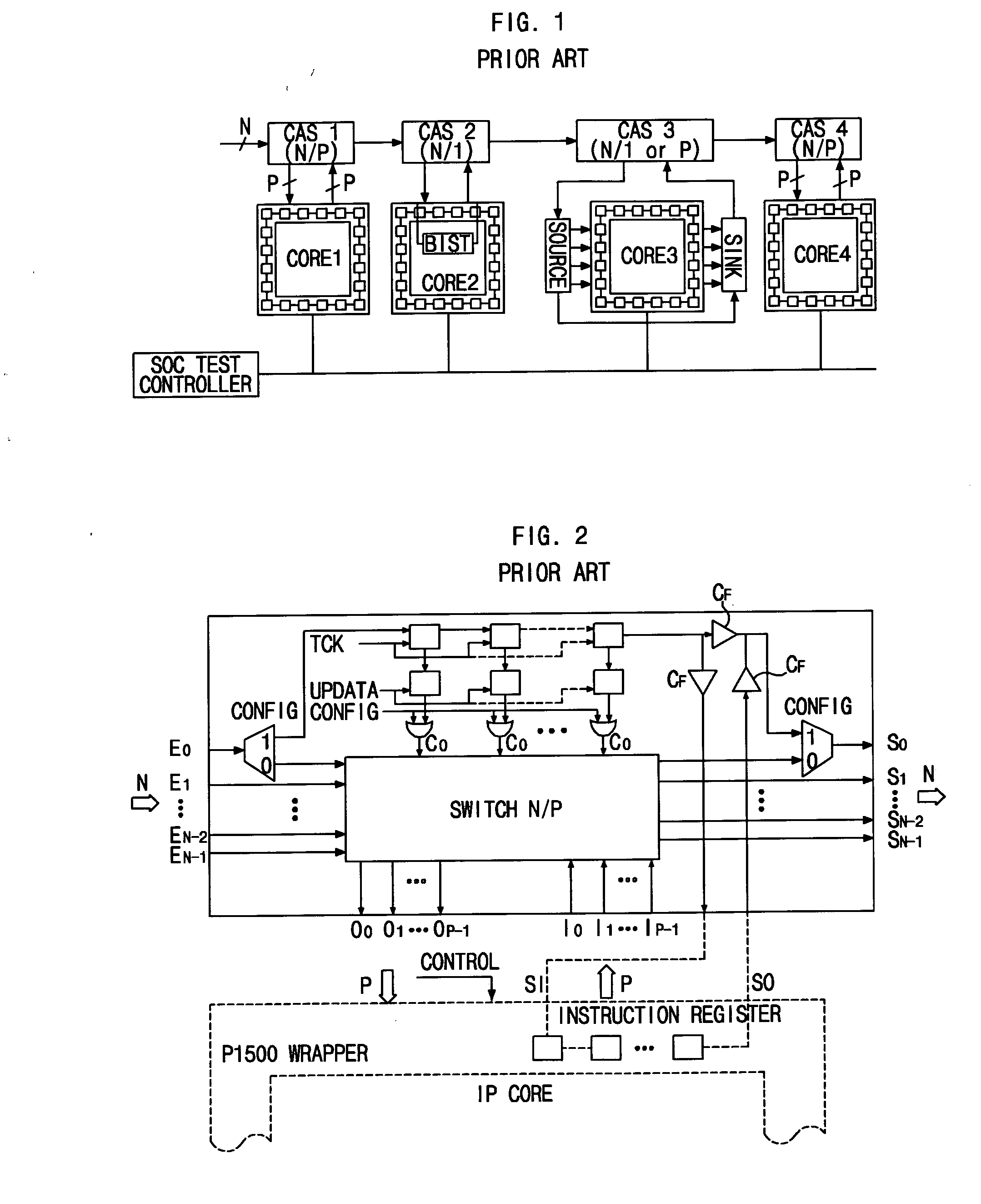
However, the structure of the CAS is complicated, so that the actual application of the CAS-BUS to a system chip incurs high costs.
However, the CAS-based TAM control technology is disadvantageous in that the structure of the CAS becomes complicated as the width of test buses and the number of core scan chains increase.
The number of cases of selectively linking N test bus terminals to P scan chain input / output terminals in consideration of order is NPP (N Permutation P), which should be supported by a CAS configuration instruction, so that the design of the CAS becomes very complicated.
Such CAS is problematic in that it is difficult for the CAS to be applied to an actual commercial Application-Specific Integrated Circuit (ASIC) in which the number of scan chains is several tens or more and the total number of scan cells is several hundreds of thousands.

Method used


Image

  • Soc-based core scan chain linkage switch
  • Soc-based core scan chain linkage switch
  • Soc-based core scan chain linkage switch

Examples


Embodiment Construction

[0019] A preferred embodiment of the present invention is descried in detail with reference to the accompanying drawings below.

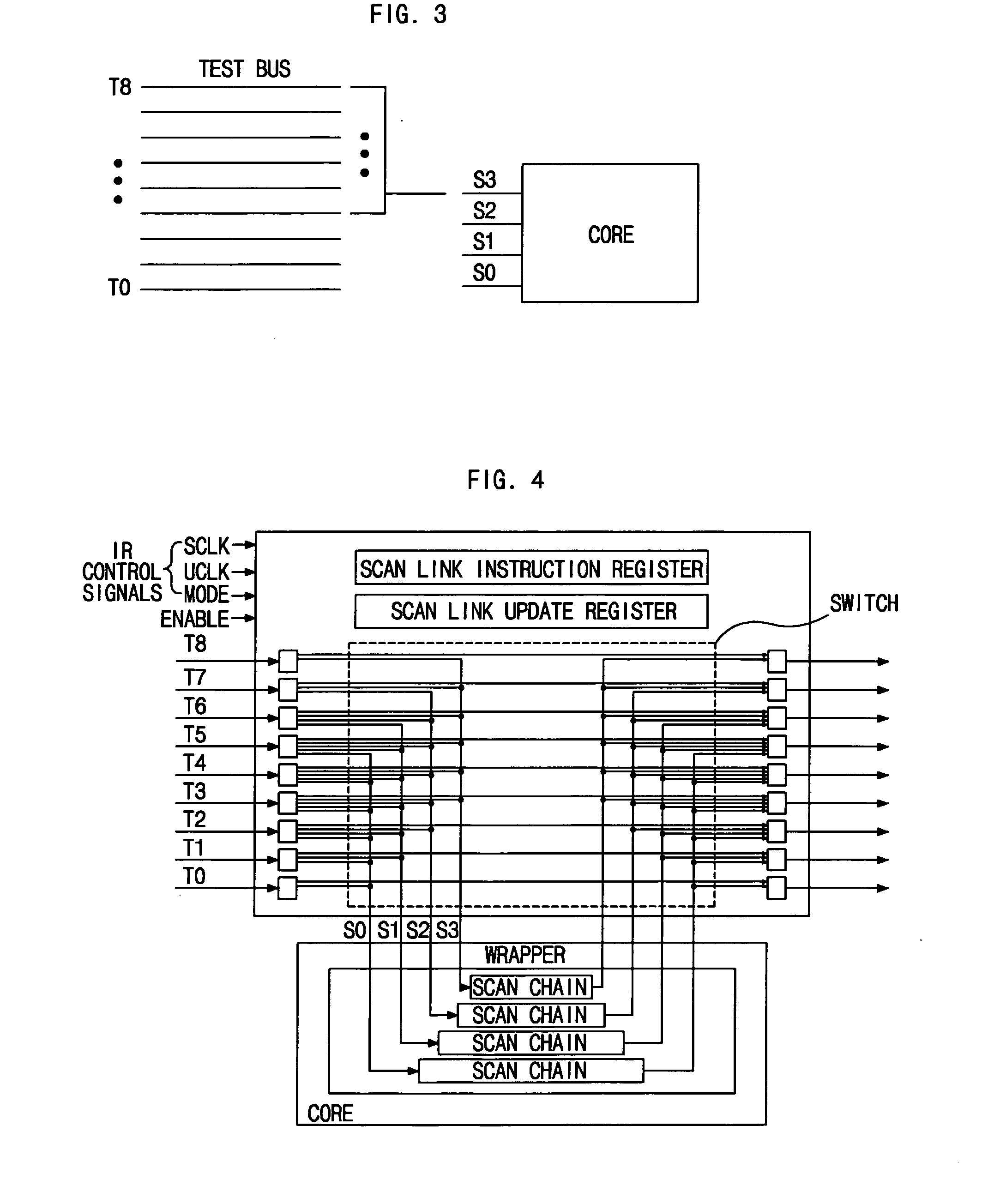
[0020] When linking N test bus terminals to P scan chain input terminals, the core scan chain linkage switch of the present invention considerably reduces the number of cases of linkage between pins to (N−P+1)P by restricting the linkage of each scan pin to (N−P+1) test pins in such a way as to link an upper scan pin to an upper test pin in consideration of the order of arrangement of pins, thereby significantly reducing complexity compared to the conventional CAS.

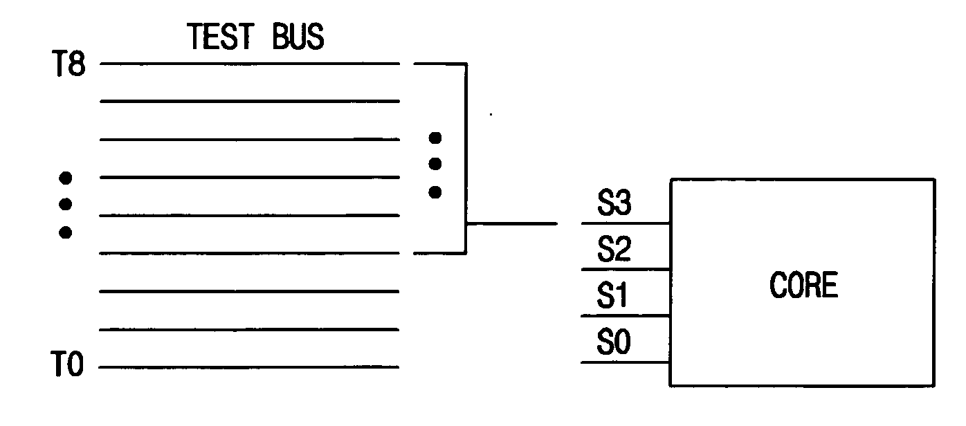
[0021]FIG. 3 is a diagram showing an example of restricting the reconfiguration range of the core scan chain linkage switch. As shown in FIG. 3, in the case where the number of test pins is nine and the number of scan pins is four, wiring can be optimized by analyzing design information after the arrangement of an SoC has been completed and restricting the linkage of the uppermost scan pin S3 to ...


PUM


Abstract

Disclosed herein is an SoC-based core scan chain linkage switch. The core scan chain linkage switch includes test bus terminals, scan chain input / output terminals, a switch unit and SCLK, UCLK, Mode and Enable signals. The test bus terminals apply instructions and input / output test data. The scan chain input / output terminals link with the scan chains of an embedded core. The switch unit completes a linkage configuration between the test bus terminals and the scan chain input / output terminals in response to the applied instructions. The SCLK, UCLK and Mode signals apply the instructions to dynamically reconfigure the switch unit and update the linkage configuration of the switch unit, and the Enable signal activates and deactivates the switch unit.

Description

RELATED APPLICATIONS [0001] The present disclosure relates to subject matter contained in priority Korean Application No. 10-2003-0086700, filed on 2 Dec. 2003, which is herein expressly incorporated by reference in its entirety. BACKGROUND OF THE INVENTION [0002] 1. Field of the Invention [0003] The present invention relates generally to a system-on-a-chip-based scan chain linkage switch and, more particularly, to a test access mechanism (TAM) that facilitates the various dynamic tests by guaranteeing reconfiguration capability while minimizing the hardware overhead of the test access configuration of intellectual property cores embedded in a system-on-a-chip. [0004] 2. Description of the Related Art [0005] As the degree of integration of a chip rapidly increases recently with the help of the development of semiconductor technology, a System-on-a-Chip (SoC) in which a system composed of cores, such as a processor and memory, is implemented in a single chip is widely used. The perio...

Claims


Application Information

Patent Timeline
IPC IPC(8): G06F11/26G01R31/28G01R31/3185
CPCG01R31/318558G06F11/26
Inventor PARK, CHANG WONJEON, KI MANPARK, SUNG JUYEOM, KYEONG WONKIM, TAE SIK
Owner KOREA ELECTRONICS TECH INST
Learn More