Intake apparatus for engine

a technology for a ram and an intake apparatus, which is applied in the direction of machines/engines, combustion-air/fuel-air treatment, and separation processes to achieve the effects of enhancing the air intake effect on the center, effective ram pressure, and effectively utilizing the ram pressur

Inactive Publication Date: 2005-07-14
HONDA MOTOR CO LTD
View PDF0 Cites 32 Cited by
  • Summary
  • Abstract
  • Description
  • Claims
  • Application Information

AI Technical Summary

Benefits of technology

[0018] In another embodiment of the invention, an arrangement is provided so that air intake passages open in the vicinity of a bottom bridge (for example, a bottom bridge 36 in the embodiment) supporting a front fork (for example, a front fork 21 in the embodiment), and tip ends of the air intake passages are fixed to an upper portion of a radiator (for example, a radiator 89 in the embodiment). By such an arrangement, the air can be introduced from a region in the vicinity of the bottom bridge, where the ram pressure can be obtained effectively, and it is made possible to introduce the air without being adversely affected mutually with airflow to the radiator.
[0019] In yet another embodiment of the invention, an arrangement is provided so that three air intake passages are provided. The air intake passage on a center is formed larger than the two on the sides thereof, and the two on the sides are controlled to close in a case where the air intake passage on the center opens when the engine rotates at the high speed, and controlled in a reverse order when the engine rotates at low and middle speeds. By such an arrangement, the air can be introduced from the large air intake passage on the center when the engine rotates at the high speed by effectively utilizing the ram pressure.
[0020] In another embodiment of the invention, an arrangement is provided so that the air intake passage on the center is form

Problems solved by technology

However, conventional intake apparatuses have several disadvantages.
However, water splashed b

Method used


Image

  • Intake apparatus for engine
  • Intake apparatus for engine
  • Intake apparatus for engine

Examples


Embodiment Construction

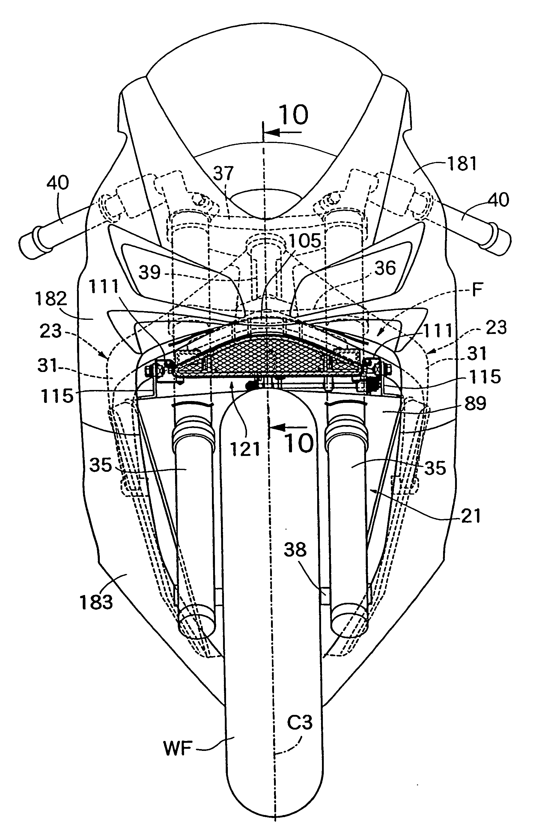
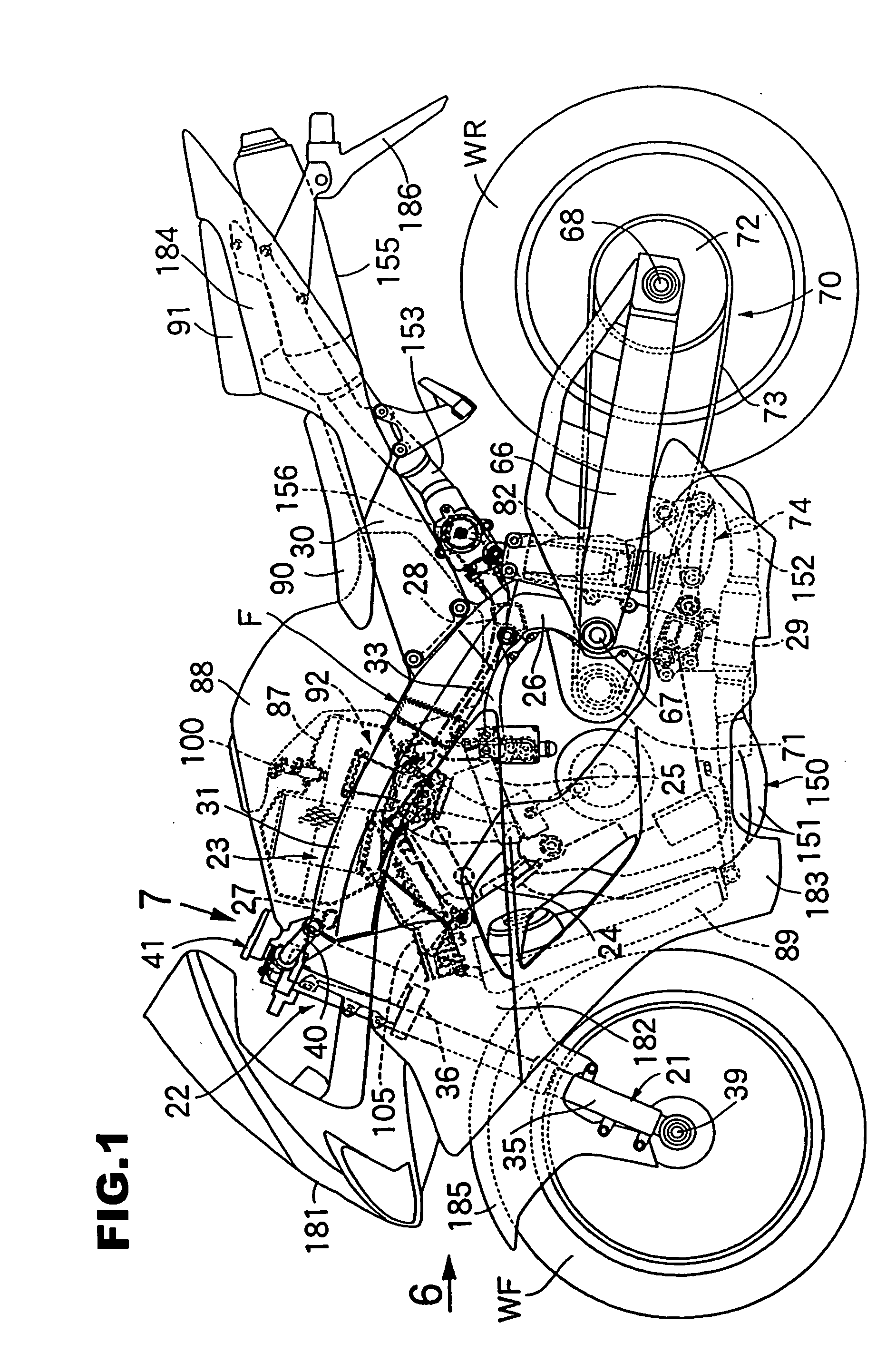
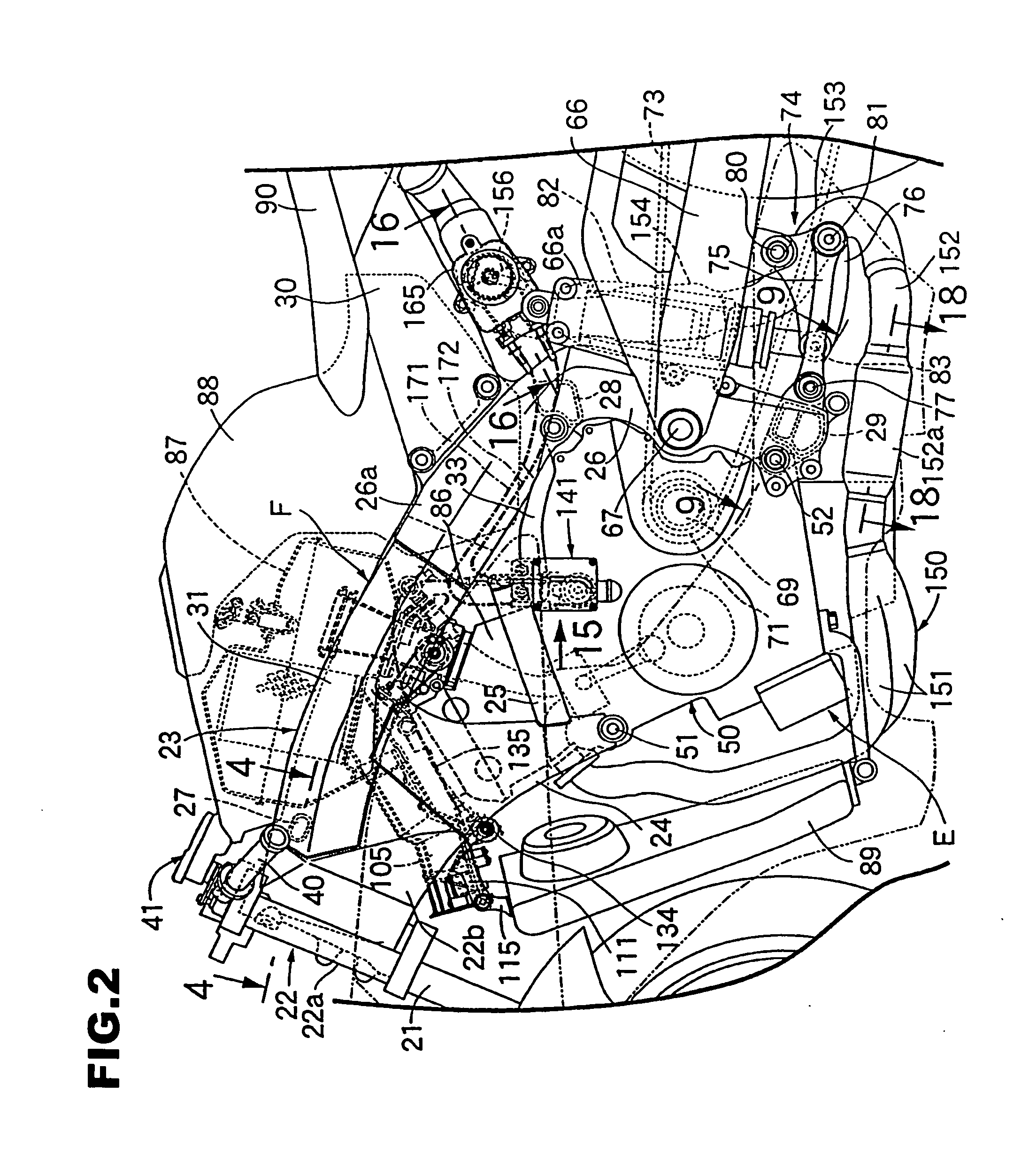
[0044] Referring to in FIGS. 1 to 3, a body frame F of this motorcycle includes a head pipe 22 steerably supporting a front fork 21 pivotally supporting a front wheel WF. Left-and-right pair of main frames 23 extend rearward and downward from the head pipe 22. A left-and-right pair of engine hangers 24 are welded to the head pipe 22 and front portions of the main frames 23 and extend downward from the main frames 23. Connecting pipes 25 connect lower portions of both the engine hangers 24 and support plate portions 33 provided on rear portions of the main frames 23, respectively. Left-and-right pivot plates 26 extend downward from the rear portions of the main frames 23. A first cross pipe 27 is hung across the front portions of the above-described main frames 23, a second cross pipe 28 is hung across upper portions of the above-described both pivot plates 26, and a third cross pipe 29 is hung across lower portions of the above-described both pivot plates 26. A left-and-right pair o...


PUM

PropertyMeasurementUnit
Timeaaaaaaaaaa
Speedaaaaaaaaaa
Widthaaaaaaaaaa

Abstract

In an intake duct, a first intake passage arranged in a width direction of the front wheel and a second intake passage arranged on a side of the first intake passage are formed such that a flow area of the first intake passage is set larger than a flow area of the second intake passage. An intake control valve closes the first intake passage when the engine rotates at low speed and opens the first intake passage when the engine rotates at high speed.

Description

BACKGROUND OF THE INVENTION [0001] 1. Field of the Invention [0002] The present invention relates to an intake apparatus for an engine for a vehicle. The present invention is particularly suitable for use in a vehicle such as a motorcycle. [0003] 2. Description of the Related Art [0004] Various intake apparatuses have been used with vehicles. For example, Japanese Patent Laid-Open No. 2001-73810 describes a conventional air cleaner that is arranged behind a head pipe provided in a front end of a motorcycle frame. An intake duct that extends forward from the air cleaner is arranged below the head pipe. However, conventional intake apparatuses have several disadvantages. It is desirable to shorten an intake duct in order to effectively introduce moving air into an air cleaner. At the same time, it is desirable to increase the opening area of the intake duct in order to increase the available power of the engine. However, water splashed by a front wheel or other foreign objects can ent...

Claims


Application Information

Patent Timeline
IPC IPC(8): F02M35/108F02D9/02F02M35/10
CPCF02B27/02F02D9/02F02M35/10013F02M35/10026F02M35/10032Y02T10/146F02M35/10216F02M35/10255F02M35/162F02M35/168F02M35/10098F02B27/0278Y02T10/12
Inventor NAKAGOME, HIROSHINAGASHI, TOSHIHISA
Owner HONDA MOTOR CO LTD
Why Eureka
Try Eureka