Tire condition monitoring system

a condition monitoring and tire technology, applied in the direction of tyre parts, process and machine control, program control, etc., can solve the problems of insufficient power saving in the method, high energy consumption in the detector, confusion among the data, etc., and achieve the effect of minimizing the power consumption of the detector

Active Publication Date: 2005-07-14
DENSO CORP
View PDF8 Cites 15 Cited by
  • Summary
  • Abstract
  • Description
  • Claims
  • Application Information

AI Technical Summary

Benefits of technology

[0008] The present invention has been made in view of the above-mentioned problems, and an object of the present invention is to provide an improved tire condition monitoring system, in which data wirelessly transmitted from other vehicles do not cause confusion with data detected by a monitoring system of his own vehicle. Another object of the present invention is to provide a tire condition monitoring system, in which power consumption in detectors is minimized.

Problems solved by technology

Therefore, energy consumption in the detectors become high, and a battery having a high capacity has to be installed to each detector.
In addition, the detected data may be simultaneously transmitted from plural detectors to the monitor, causing confusion among the data.
In those proposed systems, however, the following problems are involved.
If this happens, data detected by detectors of other vehicles, which are wirelessly transmitted, may be received by the monitor of his own vehicle, causing confusion with the data detected by the detector of his own vehicle.
This trouble may be caused by the detector signals from other vehicles when his monitor does not send the initiation signal to his detector.
Further, though it is conventionally proposed to decrease the power consumption in the detectors by operating the detectors for a limited time period, the amount of power saved in that method is not sufficiently large.

Method used


Image

  • Tire condition monitoring system
  • Tire condition monitoring system
  • Tire condition monitoring system

Examples


first embodiment

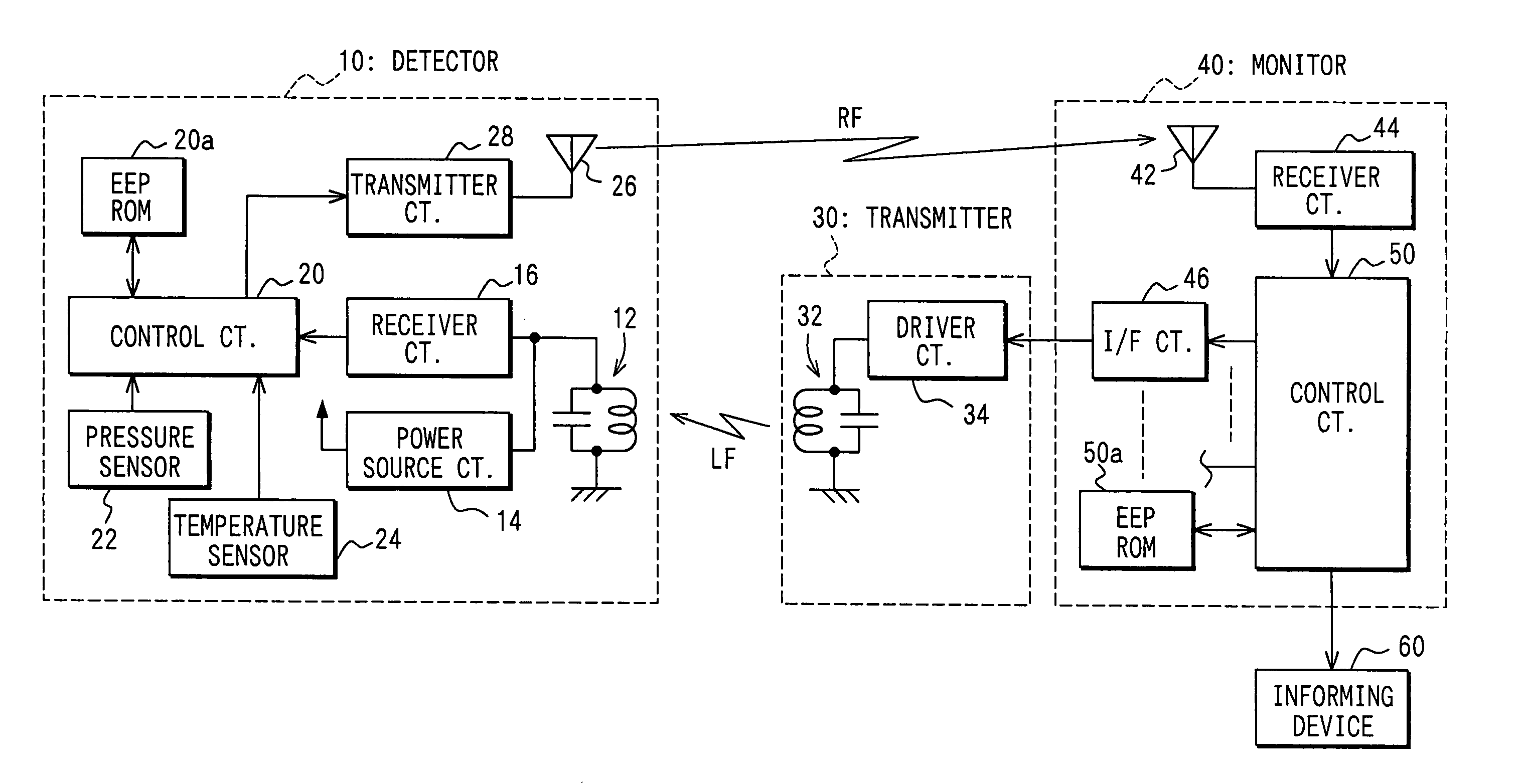
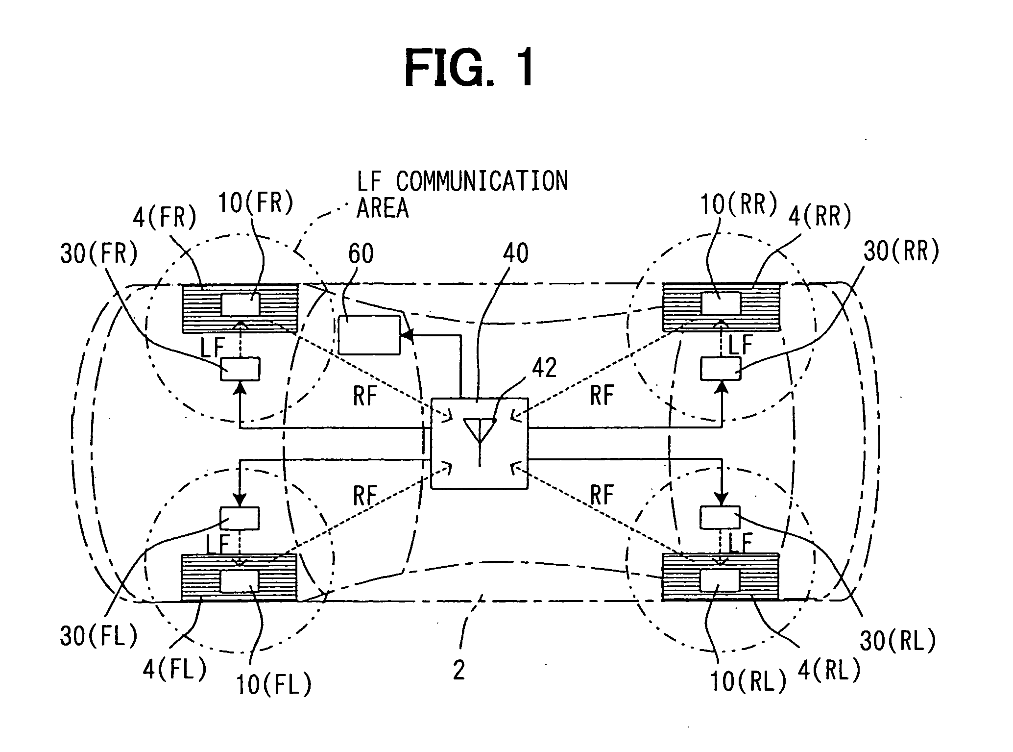
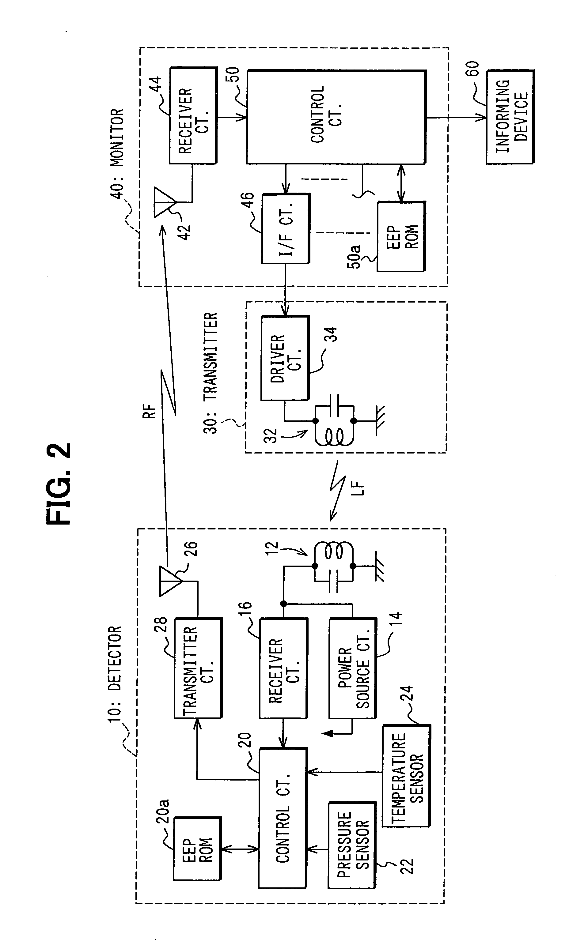
[0029] the present invention will be described with reference to FIGS. 1-5. As shown in FIG. 1, a tire condition monitoring system according to the present invention is composed of: a detector 10 installed in each tire 4 of an automotive vehicle 2; a transmitter 30 positioned in the vicinity of each tire 4; a monitor 40 mounted on the vehicle; and an informing device 60. The tire 4 includes a front left tire 4(FL), a front right tire 4(FR), a rear left tire 4(RL) and a rear right tire 4 (RR). The detector 10 includes a front left detector 10 (FL), a front right detector 10 (FR), a rear left detector 10 (RL) and a rear right detector (RR). The transmitter 30 includes a front left transmitter 30(FL), a front right transmitter 30(FR), a rear left transmitter 30(RL) and a rear right transmitter 30(RR). Since all of the detectors 10 are identical, each of the detectors 10 will be simply referred to as a detector 10. Similarly, since all of the transmitters 30 are identical, each of the t...


PUM

PropertyMeasurementUnit
radio frequencyaaaaaaaaaa
frequencyaaaaaaaaaa
pressureaaaaaaaaaa

Abstract

A tire condition monitoring system is composed of a detector installed in each tire, a transmitter positioned in the vicinity of each tire, and a monitor communicating with the transmitters and the detectors. An initiation signal for initiating operation of the detector is wirelessly sent from the transmitter to the detector, using a low frequency, and the pressure and temperature data detected by the detector are wirelessly sent to the monitor, using a radio frequency. A vehicle identification code differentiating the vehicle from other vehicles may be included in the initiation signal to avoid confusion with signals wirelessly sent from other vehicles. The detector is operated only when the tire condition data from that detector are required to minimize power consumption in the detector.

Description

CROSS-REFERENCE TO RELATED APPLICATIONS [0001] This application is based upon and claims benefit of priority of Japanese Patent Applications No. 2004-4366 filed on Jan. 9, 2004 and No. 2004-11170 filed on Jan. 19, 2004, the contents of which are incorporated herein by reference. BACKGROUND OF THE INVENTION [0002] 1. Field of the Invention [0003] The present invention relates to a tire condition monitoring system for use in an automotive vehicle, the system wirelessly detecting tire conditions including pressure and temperature in a tire. [0004] 2. Description of Related Art [0005] A tire condition monitoring system, in which tire conditions such as pressure and temperature in each tire are detected and the data are wirelessly transmitted to an on-board monitor, has been known hitherto. The detected data transmitted to the monitor are informed to a driver of the vehicle to enhance driving safety. Generally, in this kind of monitoring system, a detector installed in each tire is autom...

Claims


Application Information

Patent Timeline
Patent Type & Authority Applications(United States)
IPC IPC(8): B60C23/02B60C23/00B60C23/04
CPCB60C23/0413B60C23/0464B60C23/0416B60C23/0442C08J7/04C09D127/18C09D183/04C08J2379/08
Inventor TSUJI, HIROYUKIMURAYAMA, KOJIOKUMURA, RYOZO
Owner DENSO CORP
Why Eureka
Try Eureka