Inkjet printing device, method and computer program product for controlling ejection restoring system

a technology of ejection restoring system and printing device, which is applied in printing and other directions, can solve the problems of interference between the printing device, the wiper blade and the suction cap

Active Publication Date: 2005-07-14
BROTHER KOGYO KK
View PDF1 Cites 3 Cited by
  • Summary
  • Abstract
  • Description
  • Claims
  • Application Information

AI Technical Summary

Benefits of technology

[0020] With this structure it is possible to securely prevent the wiping member and the sucking device from interfere with together (i.e. knocking each other).

Problems solved by technology

However, the inkjet printing device has a drawback that the wiper blade and the suction cap interfere with each other if detection errors occur in detecting position of the wiper blade and the suction cap because the wiper blade and the suction cap are controlled individually.
If the wiper blade and the suction cap interfere with each other, they are damaged.

Method used


Image

  • Inkjet printing device, method and computer program product for controlling ejection restoring system
  • Inkjet printing device, method and computer program product for controlling ejection restoring system
  • Inkjet printing device, method and computer program product for controlling ejection restoring system

Examples


Embodiment Construction

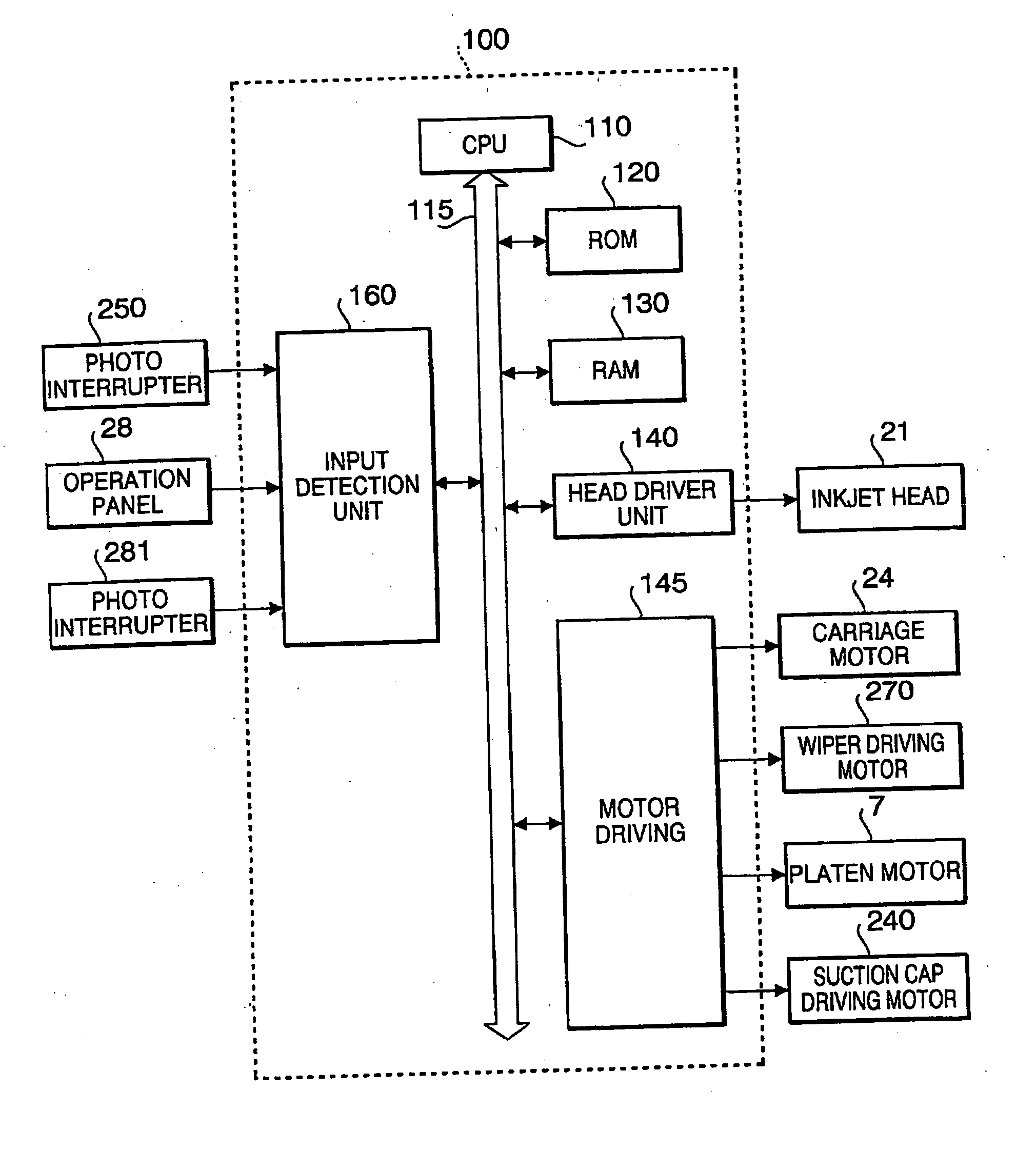
[0037] Hereafter, an embodiment according to the invention will be described with reference to the accompanying drawings.

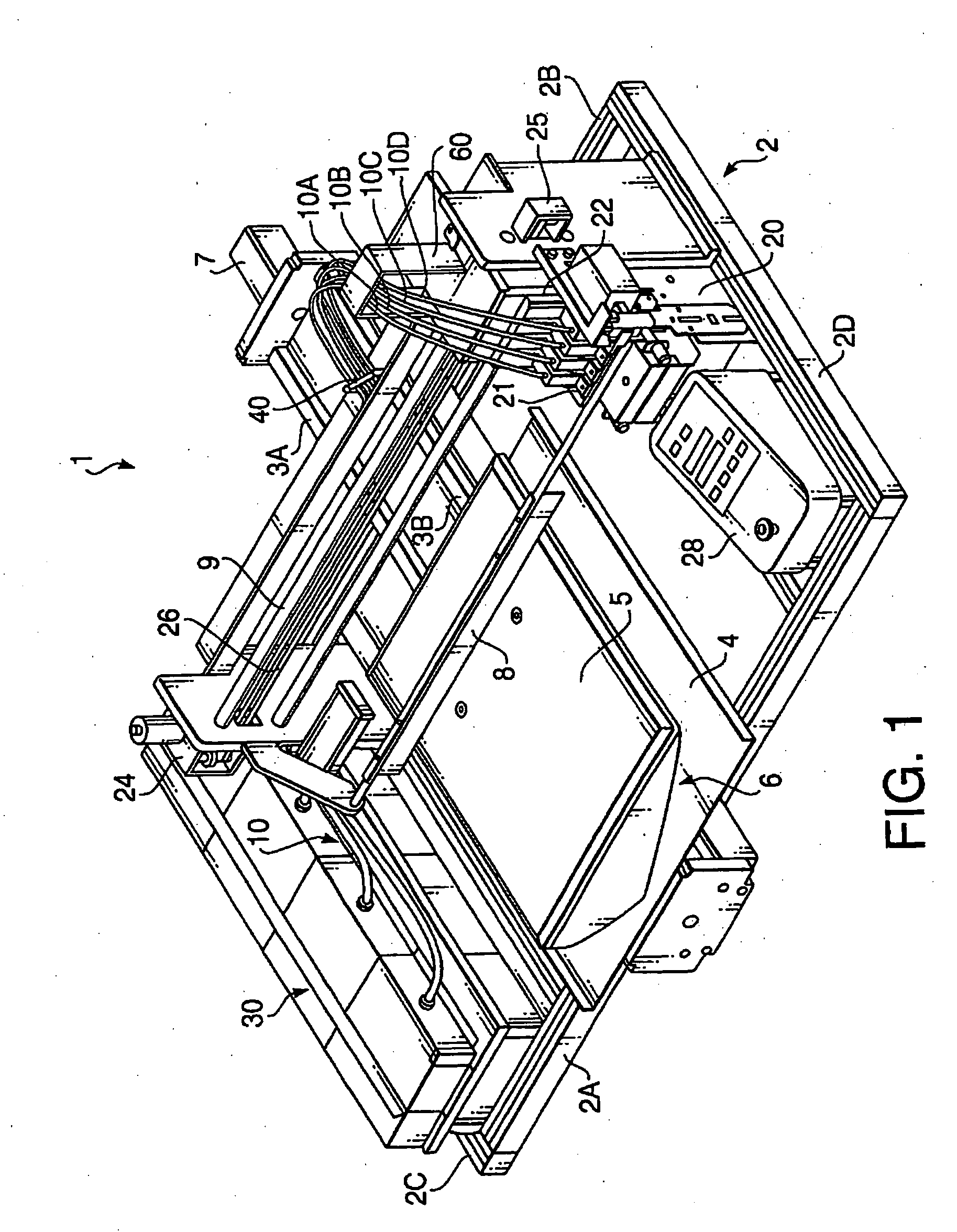
[0038]FIG. 1 is a perspective view of an inkjet printing device 1 according to an embodiment of the invention illustrating the entire configuration of the inkjet printing device 1. The inkjet printing device 1 is configured to form images or designs on a substrate such as fabric (T-shirt and etc.).

[0039] As shown in FIG. 1, the inkjet printing device 1 includes a frame 2 having a rectangular form. The frame 2 includes a front frame 2A, a rear frame 2B, a left frame 2C and a right frame 2D, each of which has a form of a rectangular column and is made of aluminum. In the following explanation, a direction parallel with the left and right frames 2C and 2D is called a back-and-forth direction, and a direction parallel with the front and rear frames 2A and 2B is called a lateral direction.

[0040] The inkjet printing device 1 includes a platen 5 and a platen driving m...


PUM


Abstract

There is provided an inkjet printing device, which is provided with an inkjet head and an ejection restoring system. The ejection restoring system includes a sucking device, a sucking device moving mechanism, a wiping member, a wiping member moving mechanism, and a driving system that drives the sucking device and the wiping member through the sucking device moving mechanism and the wiping member moving mechanism so that one of the sucking device and the wiping member is not driven if the sucking device and the wiping member interfere with each other. The driving system includes a first position detecting system that outputs a first state signal indicating that the sucking device and the wiping member interfere with each other and outputs a second state signal indicating that the sucking device and the wiping member do not interfere with each other, and a controller that controls at least one of the sucking device and the wiping member based on an output of the first position detecting system.

Description

INCORPORATION BY REFERENCE [0001] This application claims priority of Japanese Patent Application No. 2004-007397, filed on Jan. 14, 2004, the entire subject matter of the application is incorporated herein by reference thereto. BACKGROUND OF THE INVENTION [0002] The present invention relates to an inkjet printing device. More specifically, the present invention relates to an inkjet printing device having a wiper blade used to wipe ink off a nozzle surface. [0003] Inkjet printing devices configured to eject ink from nozzles formed on an inkjet head and to have a wiper blade for wiping the ink off a nozzle surface have been widely used. Each of Japanese Patent Provisional Publications No. 2000-153622 and No. 2000-280484 discloses such an inkjet printing device. To prevent ejection of the ink from being affected by residual ink remaining on the nozzle surface, the inkjet printing device is configured to wipe the residual ink off the nozzle surface by the wiper blade. [0004] The inkjet...

Claims


Application Information

Patent Timeline
Patent Type & Authority Applications(United States)
IPC IPC(8): B41J2/18B41J2/165B41J2/185
CPCB41J2/165B41J2/16541B41J2/16538B41J2/16579
Inventor OKU, NOBUAKIOZAWA, TOSHINOBU
Owner BROTHER KOGYO KK
Why Eureka
Try Eureka