Elastic crawler

a crawler and elastic technology, applied in the field of elastic crawlers, can solve the problems of deteriorating rigidity of elastic crawlers, stress on elastic crawlers, deteriorating reliability and durability of elastic crawlers, etc., to prevent vibration generation, secure the release of crawlers, and increase rigidity and flexibility

Inactive Publication Date: 2007-05-24
XENITH TRACK
View PDF6 Cites 4 Cited by
  • Summary
  • Abstract
  • Description
  • Claims
  • Application Information

AI Technical Summary

Benefits of technology

[0030] With the above structure, as the lugs are arranged left and right to the center of the crawler body in the width direction thereof, the ground contact surface of at least one of the lugs necessarily contacts the ground surface with increased contact area compared to the structure claimed in the claim 1, it becomes possible to more securely prevent the release of the crawler from the sprocket during the rotation thereof.
[0031] In short, with the structure according to the present invention, the left and right balance of the elastic crawler is enhanced with heightened rigidity and flexibility, and the vibration is prevented from being generated therein.

Problems solved by technology

However, as the iron caterpillars involve a heavy weight, a poor fuel efficiency and a loud noise, elastic crawlers have been recently introduced instead of the iron caterpillars.
However, in such an elastic crawler where the ground contact lengths of the ground contact surfaces of the left and right lugs are different from each other, the lug with a relatively short ground contact length is liable to be deteriorated in rigidity.
Furthermore, when the elastic crawler is circularly operated, the external forces applied to the left and the right lugs are differentiated, and this causes stress to the elastic crawler.
In this case, cracks are liable to be made at the stress-concentrated area, resulting in deteriorated reliability and durability of the elastic crawler.
For this reason, although slightly improved, it is not possible to obtain sufficient flexibility, and to completely remove the crawler release factor.

Method used


Image

  • Elastic crawler
  • Elastic crawler
  • Elastic crawler

Examples


first embodiment

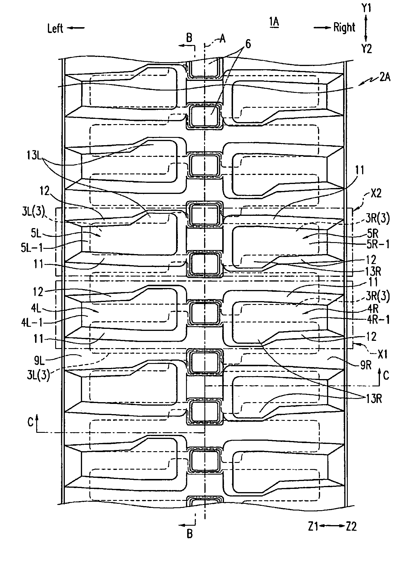
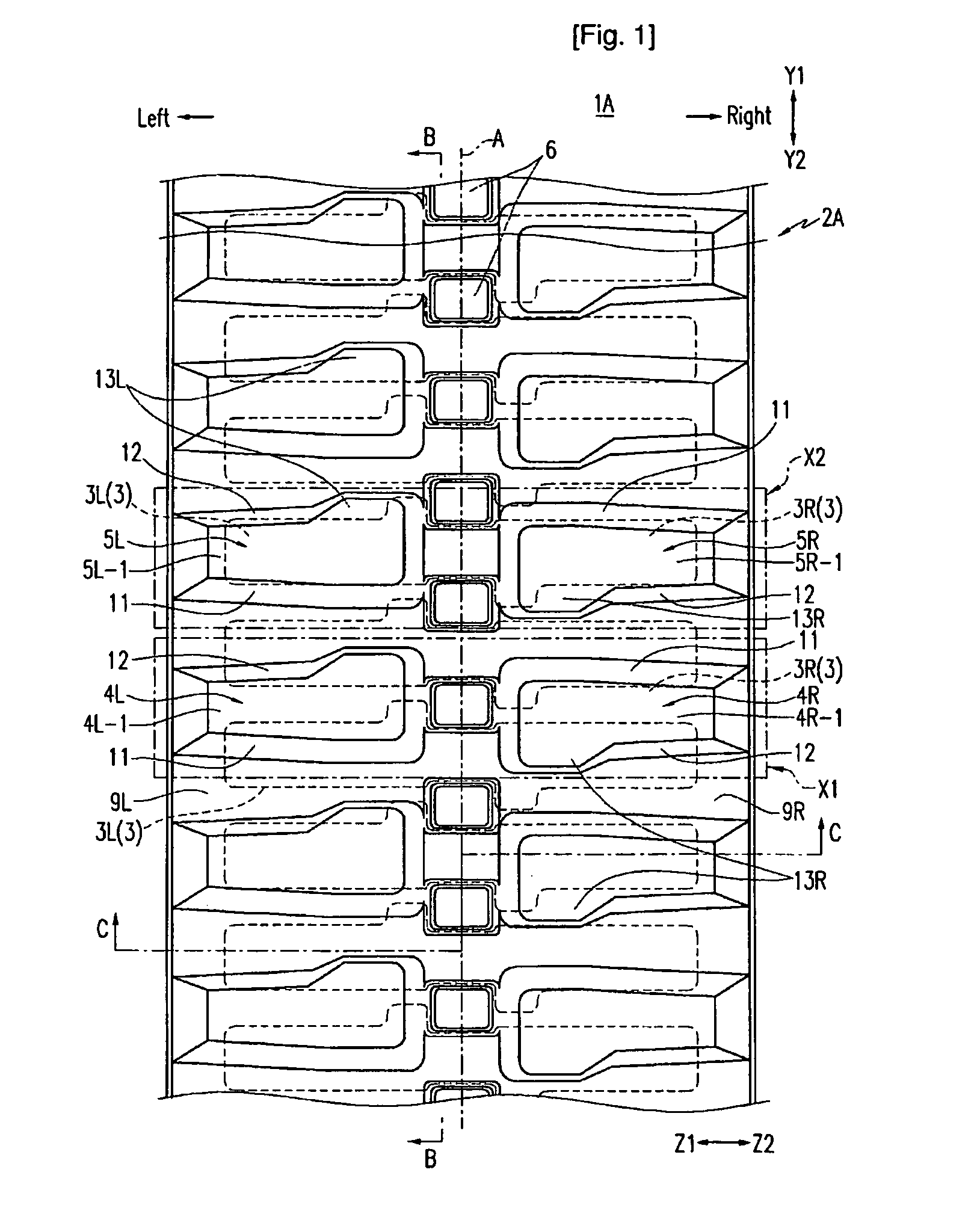
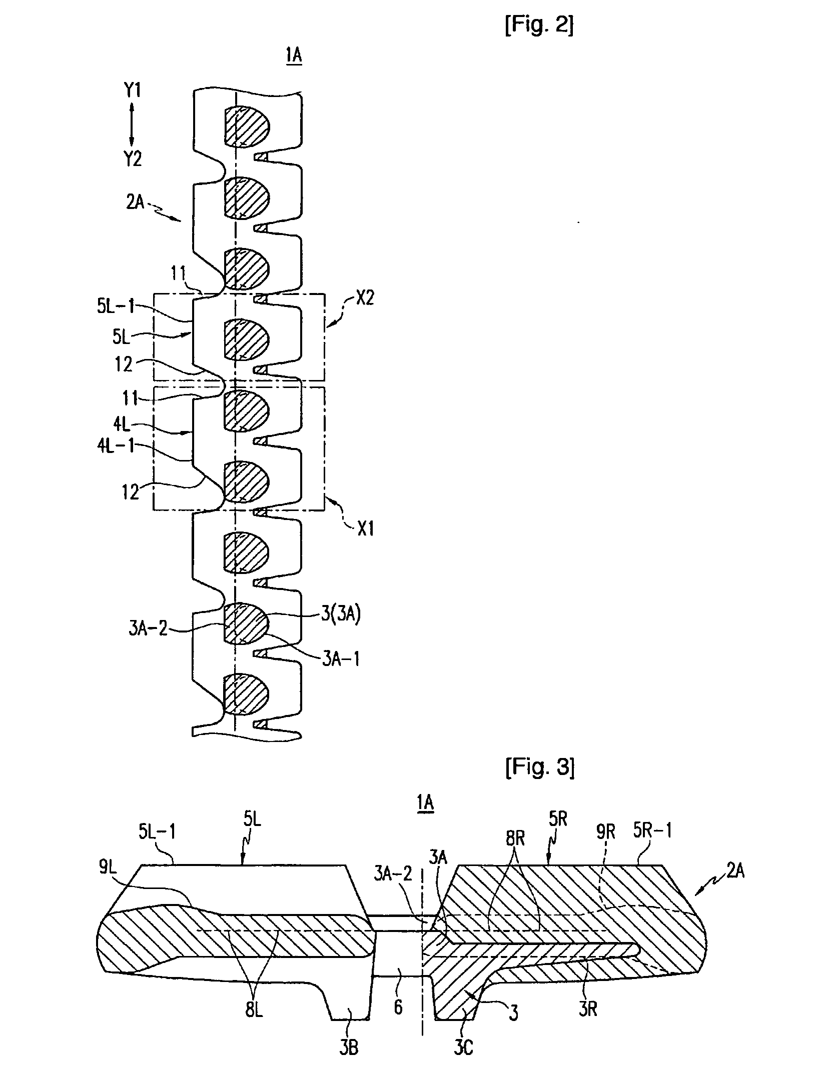
[0045] FIGS. 1 to 4 illustrate an elastic crawler 1A according the present invention. FIG. 1 is a plan view of the elastic crawler 1A, FIG. 2 is a sectional view of the elastic crawler taken along the B-B line of FIG. 1, FIG. 3 is a sectional view of the elastic crawler taken along the C-C line of FIG. 1, and FIG. 4 is a bottom view of the elastic crawler 1A.

[0046] The elastic crawler 1A is, for instance, used as the wheel for the work vehicle under the bad working conditions, such as steep and rough roads. The elastic crawler 1A is shaped with an endless track (a ring) as in the caterpillars, but for convenience, only a part of the elastic crawler 1A is amplified, and illustrated.

[0047] Roughly speaking, the elastic crawler 1A has a crawler body 2A, and cores 3. The crawler body 2A is formed with an elastic material (elastomer), such as rubber, and has a shape of an endless track. As shown in FIGS. 1 to 5, a plurality of lugs 4L, 4R, 5L and 5R, connection holes 6, and earth remova...

second embodiment

[0083] An elastic crawler according to the present invention will be now explained.

[0084] FIGS. 6 to 9 illustrate an elastic crawler 1B Wording to a second embodiment of the present invention. FIG. 6 illustrates a plan view of the elastic crawler 1B (indicated by PL in the drawing), and a bottom view thereof (indicated by BA in the drawing). FIG. 7 is a cross sectional view of the elastic crawler taken along the C-C line of FIG. 6. FIG. 8 is a plan view of the elastic crawler 1B in the presence of cores 3, and FIG. 9 is a plan view of the elastic crawler 1B shown in FIG. 8 in the absence of the cores 3. In FIGS. 6 to 9, like reference numerals will refer to the same components of the elastic crawler 1B as those of the elastic crawler 1A illustrated in FIGS. 1 to 5 according to the first embodiment of the present invention, and explanations thereof will be omitted. The elastic crawler 1A according to the first embodiment of the present invention includes a first lug unit X1 with a pa...


PUM


Abstract

Disclosed is an elastic crawler formed with an elastic material in the shape of an endless track, and used as the wheel for the work vehicle with enhanced reliability and durability. The elastic crawler includes a crawler body 2A formed with an elastic material and having lugs 4L, 4R, 5L and 5R protruded at the ground contact side thereof, and cores 3 having wings 3L and 3R extended left and right to the center of the crawler body in the width direction thereof, and arranged parallel to each other in the longitudinal track direction of the crawler body such that the wings face the lugs formed at the crawler body. The crawler body has first and second lug units alternately arranged parallel to each other in the longitudinal track direction thereof (in the direction of Y1 and Y2). The first lug unit has left lugs 4L facing each other over two wings, and right lugs 4R arranged right to the center of the crawler body while proceeding symmetrical to the left lugs around the center. The second lug unit has left lugs 5L facing each other over one wing, and right lugs 5R arranged right to the center of the crawler body while proceeding symmetrical to the left lugs around the center.

Description

TECHNICAL FIELD [0001] The present invention relates to an elastic crawler, and in particular, to an elastic crawler which is formed with an elastic material while taking a shape of an endless track, and used as the wheel of the work vehicle under bad working conditions, for example, on the steep and rough road. BACKGROUND ART [0002] Generally, iron caterpillars have been commonly used as the wheels for the work vehicles under the bad working conditions, such as a steep and rough road condition. However, as the iron caterpillars involve a heavy weight, a poor fuel efficiency and a loud noise, elastic crawlers have been recently introduced instead of the iron caterpillars. [0003] The elastic crawler has a crawler body, and cores. The crawler body is based on an elastic material with a shape of an endless track. The cores are embedded in the crawler body with right and left wings extended left and right from the center of the crawler body, that is, in the width direction of the crawle...

Claims


Application Information

Patent Timeline
Patent Type & Authority Applications(United States)
IPC IPC(8): B62D55/24B62D55/253
CPCB62D55/24B62D55/253
Inventor CHOI, YONG JAE
Owner XENITH TRACK
Why Eureka
Try Eureka