Shut-off device for pipes

Inactive Publication Date: 2001-03-20
PRAZISIONSARMATUREN OSTFALENPARK BARLEBEN
View PDF11 Cites 9 Cited by
  • Summary
  • Abstract
  • Description
  • Claims
  • Application Information

AI Technical Summary

Benefits of technology

is therefore to provide a shut-off device for pipes of the type mentioned above by means of which tubes of big nominal diameters, that may be locked by slide valves, may be sealed up against their environme

Problems solved by technology

As already mentioned at the beginning, the sealing of shut-off devices for pipes by means of slide valves in housings having a big diameter is very complicated.
Long expansion bellows could not be used for sealing, since

Method used


Image

  • Shut-off device for pipes
  • Shut-off device for pipes
  • Shut-off device for pipes

Examples


Embodiment Construction

)

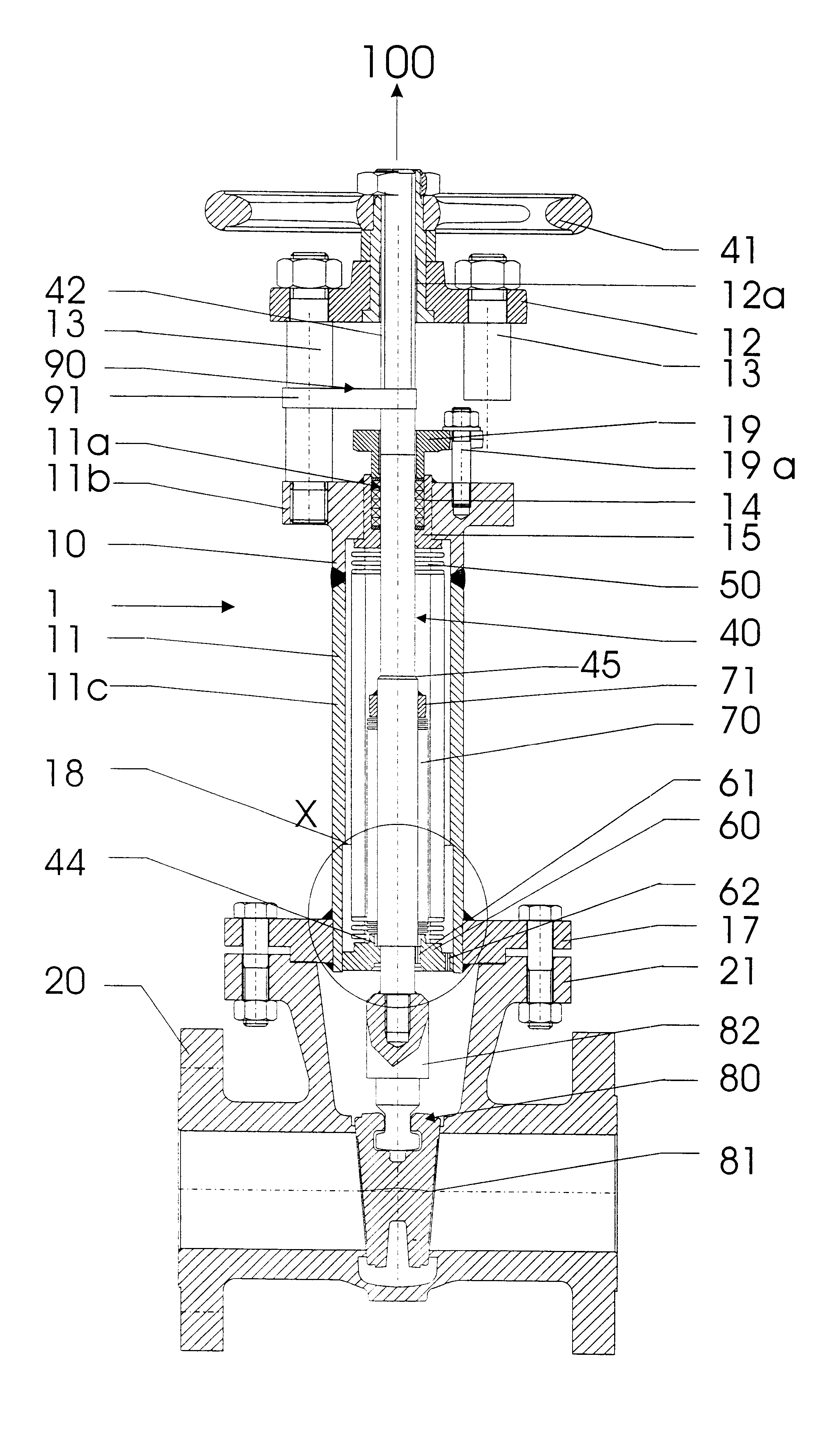
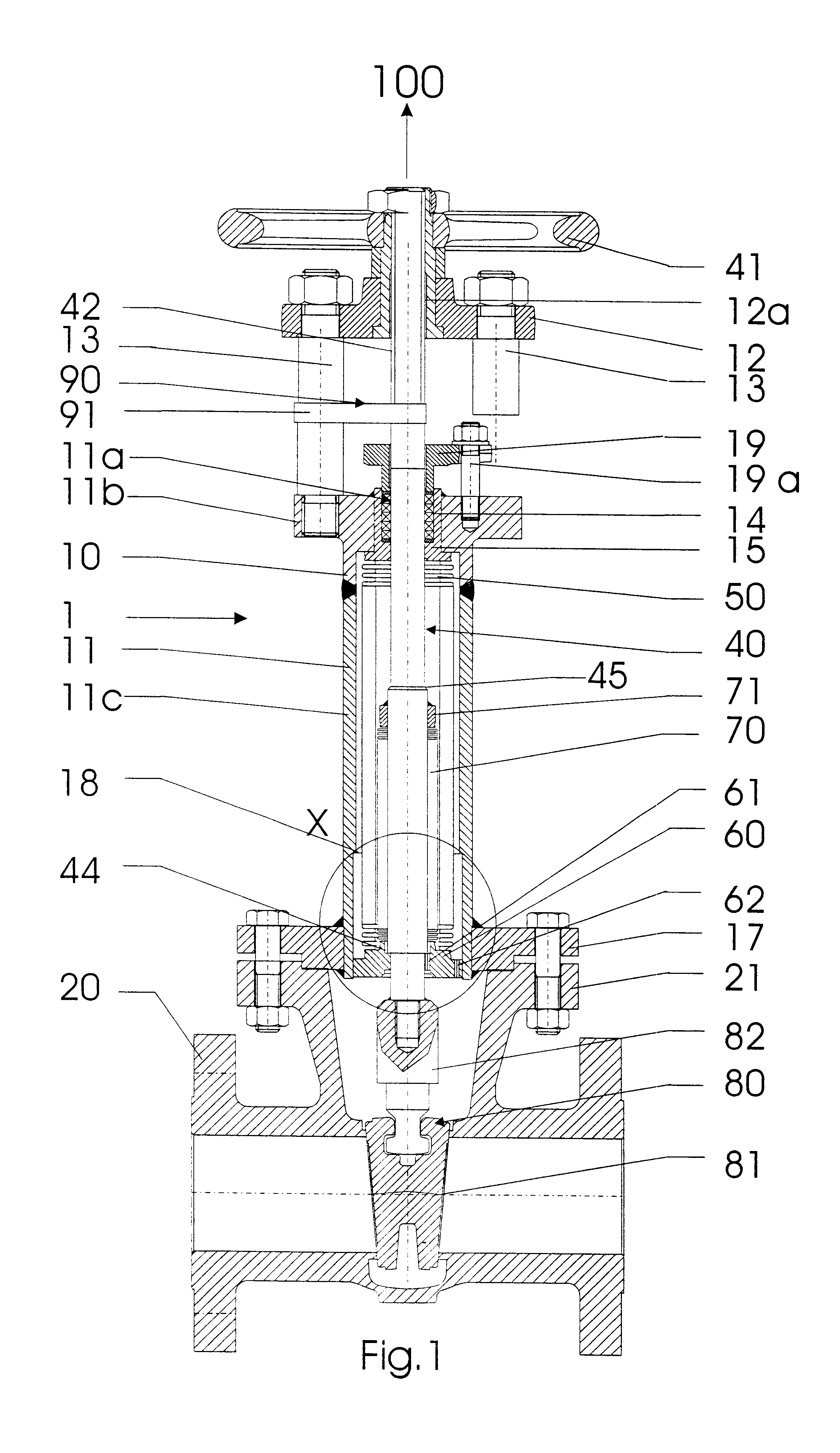
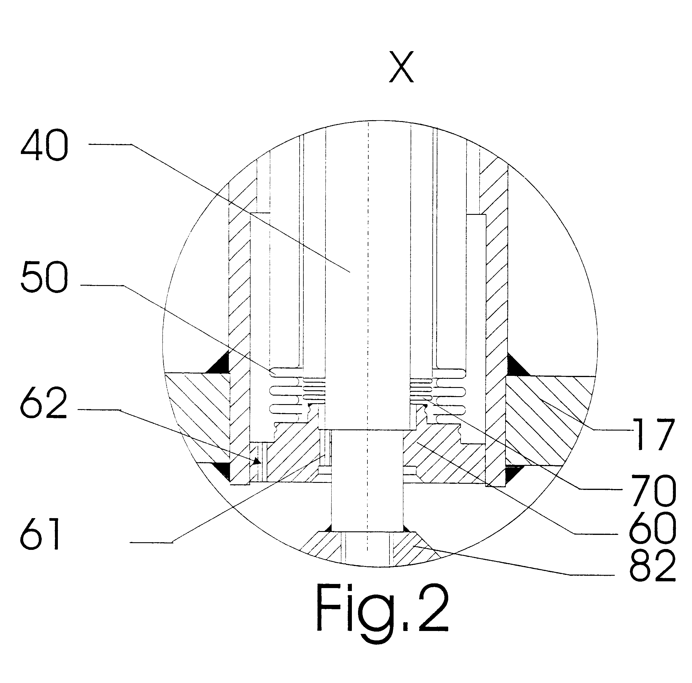
The shut-off device for pipes, referred to as a whole with numeral 1, consists of the upper part of the housing 10 and of the housing 20 with the flange 21, whereas the flange 21 is receiving the upper part of the housing 10 of the shut-off device for pipes. The upper part of the housing 10 of the shut-off device for pipes is composed of the cover 11 that is connected to the housing bridge 12 by preferably two pillars 13. On its upper part, the cover 11 has the flange 11b with the boring 11a for the spindle 40. The sleeve-type cover element 11c is attached to the flange 11b, whereas the flange serves for receiving the pillars 13. The cover 11 is provided at its lower end facing the pipe 20 with a flange 17 which is connected with the flange 21 of the housing.

The spindle, which is referred to as a whole with numeral 40, is guided in the upper part of the housing 10. The spindle, which is referred to with numeral 40, is provided on its upper end with the handwheel 41 and is guided in...


PUM


Abstract

The device is used for a shut-off device for pipes comprising a spindle communicating with a shut-off device arranged in a housing, whereas the spindle is borne in an upper part of the housing so as to be axially slidable, the upper part of the housing being provided with a cover resting on the housing, whereas the interior space of the cover is communicating with the medium led through the housing, whereas the spindle (40) is provided at its lower end facing the shut-off device (80) with a ring (60) carrying at least two concentrically arranged expansion bellows, whereas the inner expansion bellows (70) is communicating with the spindle (40) and the other outer expansion bellows (50) is communicating with the flange (11b) of the cover of the housing (11).

Description

1. Field of the InventionThe present invention concerns a shut-off device for pipes comprising a spindle communicating with a shut-off device arranged in a housing, whereas the spindle is borne in an upper part of the housing so as to be axially slidable, the upper part of the housing being provided with a cover resting on the housing, whereas the interior space of the cover is communicating with the medium led through the housing.2. Description of the Prior ArtA shut-off device of the type mentioned above has been manufactured for quite a few years. Shut-off devices for pipes, and more particularly stop slide valves, yet proved to often require big strokes as opposed to globe valves which get on well with relatively small strokes. In shut-off devices of the type mentioned above, it is indeed always necessary to completely remove the actual shut-off device, that is the key, from the open cross section of the pipe. Considerable efforts were therefore necessary to seal up the shut-off...

Claims


Application Information

Patent Timeline
IPC IPC(8): F01L1/344F01L1/348F16D3/10F16D3/02
CPCF01L1/348F16D3/10
Inventor FICHTNER, LOTHARROSAM, MARKUS
Owner PRAZISIONSARMATUREN OSTFALENPARK BARLEBEN
Why Eureka
Try Eureka