Liquid crystal display

Inactive Publication Date: 2005-07-14
SHARP KK
View PDF6 Cites 113 Cited by
  • Summary
  • Abstract
  • Description
  • Claims
  • Application Information

AI Technical Summary

Benefits of technology

[0056] In the above-described construction, when the liquid crystal display is so constructed that the light source-replacing operation can be performed easily at the rear side thereof, by merely removing the fastener at the rear side of the back chassis, it is possible to separate the back chassis from the light source-holding member and expose the light source held by the light source-holding member to the outside. Therefore the operability in the maintenance can be improved.
[0057] As apparent from the foregoing description, the liquid crystal display according to the present invention is so constructed that the group of the optical sheets is supported by the sheet-holding chassis; the group of the optical sheets is fixed to the front frame; or the group of the optical sheets is supported by the upper surface of the light source-holding member even when the back chassis is removed. Thus in the maintenance of replacing the light source which has been exposed to the outside because the back chassis has been removed, the group of the optical sheets remains held integrally. Therefore in the light source-replacing operation, it is possible to prevent the optical sheets from being separated from each other and hence dust from entering between the optical sheets. Further the construction eliminates the need for performing the light source-replacing operation in a

Problems solved by technology

Consequently there is a fear that after the light source-replacing operation finishes, dust enters the gap between the optical sheets and that the liquid crystal display deteriorates in its display quality.
Thus a service man and a user cannot perform the light source-replacing operation easily.
This method has a disadvantage that almost all unfailed component parts are replaced.
Thus this method costs high.
When the light source-replacing operation is performed by using the above-described two methods, a secondary damage may occur.
More specifically, because the liquid crystal panel is opened

Method used


Image

  • Liquid crystal display
  • Liquid crystal display
  • Liquid crystal display

Examples


first embodiment

[0122] the present invention will be described below with reference to drawings.

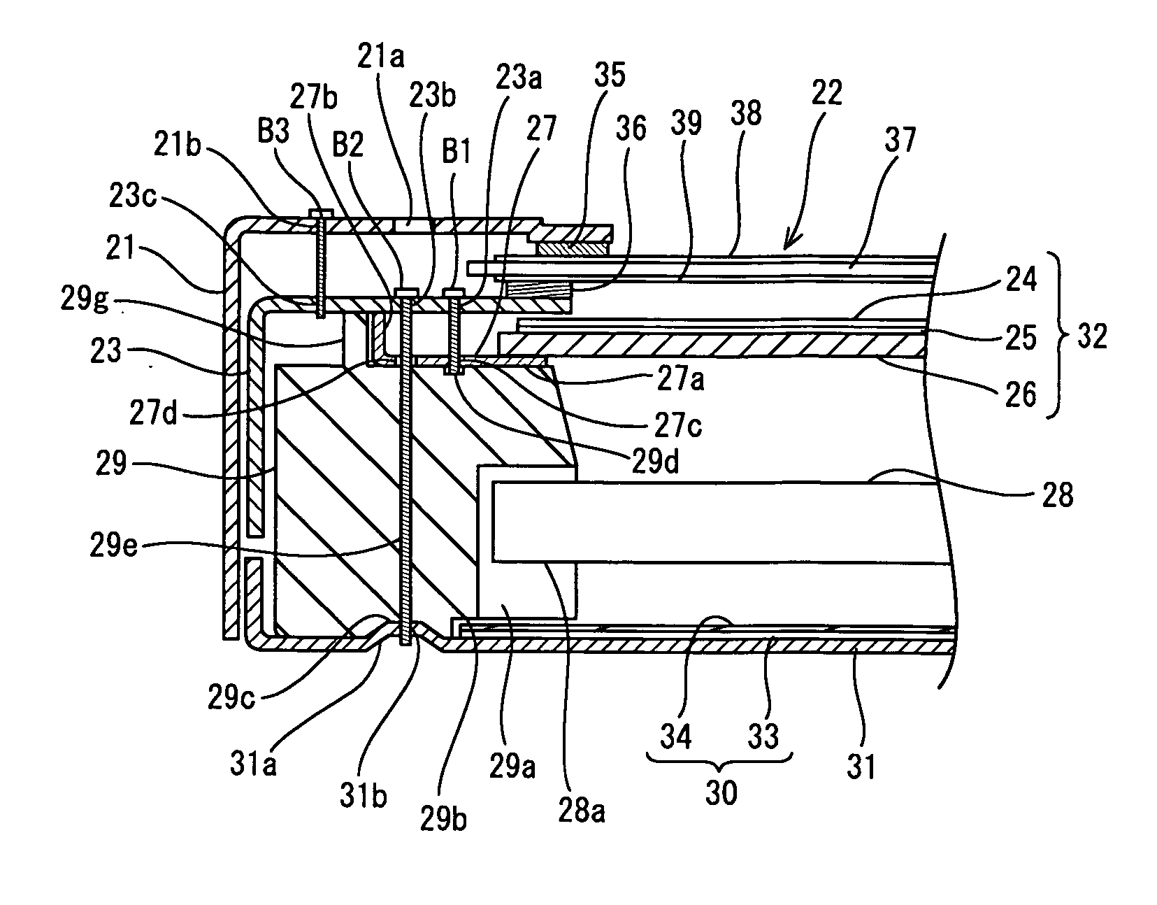
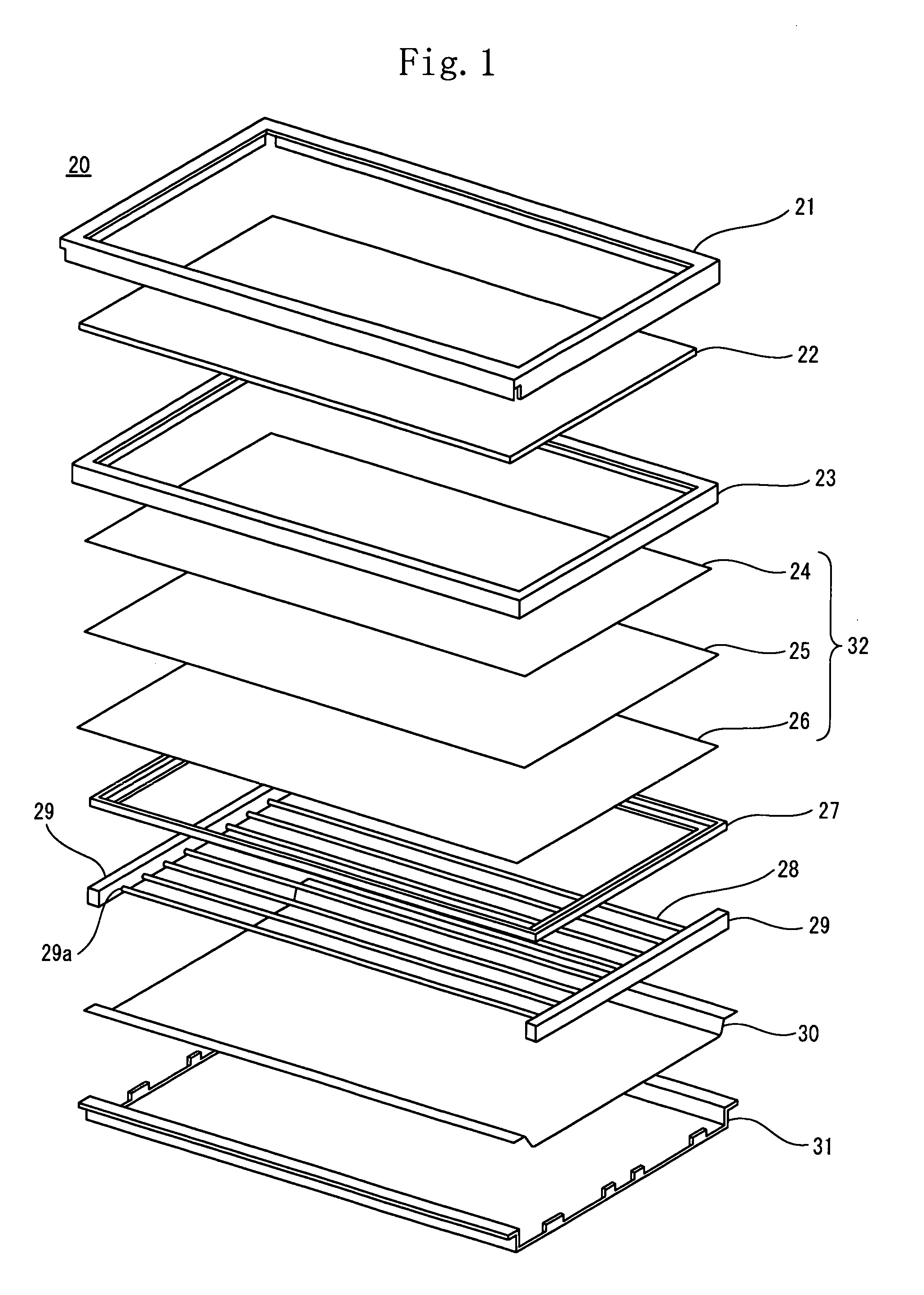
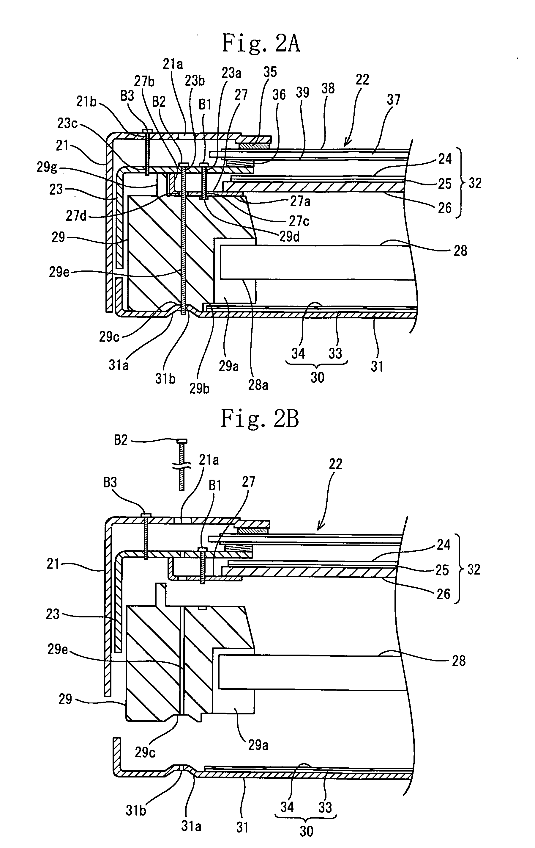
[0123] As shown in FIGS. 1 and 2A, in a liquid crystal display 20, the periphery of a liquid crystal panel 22 is held by a frame-shaped front chassis 23 and a bezel 21 through spacers 35, 36. The front chassis 23 and the bezel 21 form a front frame. A optical sheet group 32 (hereinafter referred to as optical sheet group 32) is disposed below the liquid crystal panel 22 by supporting the optical sheet group 32 with a frame-shaped sheet-holding chassis 27. A plurality of linear light sources 28 is disposed parallel with each other below the optical sheet group 32. With both ends 28a of each linear light source 28 being held with a light source-holding member 29, the linear light sources 28 are closed with a reflecting composite member 30 disposed below the light source-holding member 29 and a back chassis 31 disposed below the reflecting composite member 30. It is to be noted that the front side of the li...

second embodiment

[0140]FIGS. 3A and 3B show the

[0141] In the second embodiment, instead of the reflecting composite member 30, a reflecting sheet 42 is mounted on the upper surface of the back chassis 31. A bezel 41 has an opening 41c, formed above the screw B1, into which a screw is threaded.

[0142] The bezel 41 has openings 41a and 41c formed at a position corresponding to the position of the screw B1 and at a position corresponding to the position of the screw B2. The bezel 41 has a screw hole 41b at a position corresponding to the position of the screw B3.

[0143] In the above-described construction, when the sheet-holding chassis 27 is intended to be disassembled, the screw B2 is removed through the opening 41a of the bezel 41 to disassemble the light source-holding member 29, the reflecting sheet 42, and the back chassis 31 from each other. The screw B1 is also removed through the opening 41c of the bezel 41 to disassemble the sheet-holding chassis 27 without disassembling the bezel 41 and the ...

third embodiment

[0145]FIGS. 4A and 4B show the

[0146] In the third embodiment, the liquid crystal display is not provided with the sheet-holding chassis 27. Instead, one end of a diffusing plate 44 disposed lowermost in an optical sheet group 45 is extended sideways to provide screw holes 44a and 44b on the diffusing plate 44.

[0147] The front chassis 43 has a concave portion 43b formed at a position into which the screw B1 is threaded and has a screw hole 43d formed at the concave portion 43b. The front chassis 43 has an opening 43a formed at a position corresponding to the position of the screw B2 and has a screw hole 44c formed at a position corresponding to the position of the screw B3.

[0148] The front chassis 43 and the diffusing plate 44 disposed lowermost in the optical sheet group 45 are fixed to each other with the screw B1 threaded into the screw hole 43d and the screw hole 44b. Thereby in addition to the fixing of the diffusing plate 44 to the front chassis 43, the prism sheet 24 and the...


PUM


Abstract

A liquid crystal display comprises a liquid crystal panel (22), a group of optical sheets (32) disposed rearward from the liquid crystal panel (22), a light source (28) disposed rearward from the group of the optical sheets (32), a frame-shaped front frame (21, 23) disposed forward from at least the group of the optical sheets (32), a back chassis (31) disposed rearward from the light source (28) and fixedly connected to the front frame (21, 23) directly or indirectly, and a holding member (27) integrally holding the group of the optical sheets (32) to keep the group of the optical sheets (32) held in position integrally, when the back chassis (31) and the front frame (21, 23) are unfixed from each other.

Description

[0001] This nonprovisional application claims priority under 35 U.S.C. § 119(a) on Patent Application No(s). 2004-006797 filed in Japan on Jan. 14, 2004, the entire contents of which are hereby incorporated by reference. BACKGROUND OF THE INVENTION [0002] 1. Field of the Invention [0003] The present invention relates to a liquid crystal display in which a light source is disposed at a rear side of a liquid crystal panel. [0004] 2. Description of the Related Art [0005] In the liquid crystal display, a back light which is a flat light source is disposed at the rear side of the liquid crystal panel thereof. The “vertical” type and the “edge light” type are known as the type of the back light. In the former type, a plurality of light sources is disposed at the rear side of the liquid crystal panel. In the latter type, a light source is disposed on the side surface of the liquid crystal panel so that a light guide plate emits light flatly. The back light of the vertical type is thick but...

Claims


Application Information

Patent Timeline
IPC IPC(8): G02F1/1333F21V8/00G02F1/13G02F1/1335G02F1/13357
CPCG02F1/1309G02F1/133308G02F2203/68G02F2001/133317G02F2201/46G02F1/133608G02F1/133317G02F1/1333
Inventor KATSUDA, YASUTOSHIONOUE, MASATOIWAI, TAKAYUKIKUDARI, TATSUYA
Owner SHARP KK
Why Eureka
Try Eureka