
Joint packet detection in wireless communication system with one or more receiver

a wireless communication system and receiver technology, applied in the direction of transmission monitoring, wireless commuication services, electrical equipment, etc., can solve the problems that the receiver that must receive and process both 802.11a and 802.11b signals cannot use a simple common sampling scheme, and many conventional packet detection schemes are unsuitabl

Active Publication Date: 2005-07-14
QUALCOMM INC
View PDF27 Cites 66 Cited by
  • Summary
  • Abstract
  • Description
  • Claims
  • Application Information

AI Technical Summary

Problems solved by technology

The fact that packets with different modulations can be present within the same network creates difficulties in the design of 802.11 packet detection circuits, as they have to detect the presence of a packet with a fraction of its preamble and it has to indicate whether the packet is an 802.11a packet or an 802.11b packet with a very low probability of error.
Aside from the interference issues and packet detection issues, a receiver that must receive and process both 802.11a and 802.11b signals cannot use a simple common sampling scheme, as conventional 802.11a receivers operate at a 20 MHz sampling rate, while conventional 802.11b receivers operate at a sampling rate of 22 MHz.
With a wider expected operating range in terms of SNR, correct packet detection is expected at lower SNRs, making many conventional packet detection schemes unsuitable.

Method used


Image

  • Joint packet detection in wireless communication system with one or more receiver
  • Joint packet detection in wireless communication system with one or more receiver
  • Joint packet detection in wireless communication system with one or more receiver

Examples


Embodiment Construction

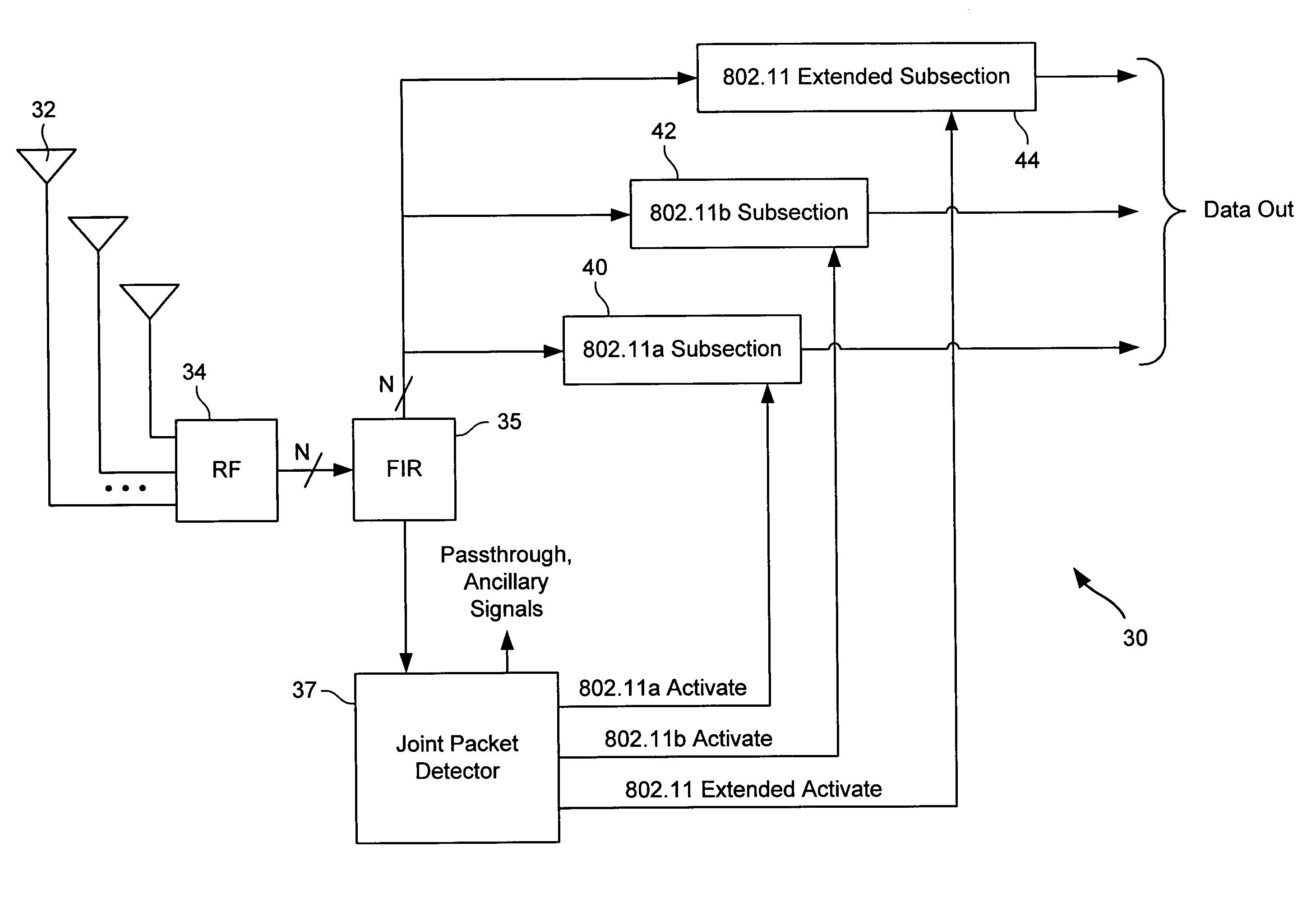
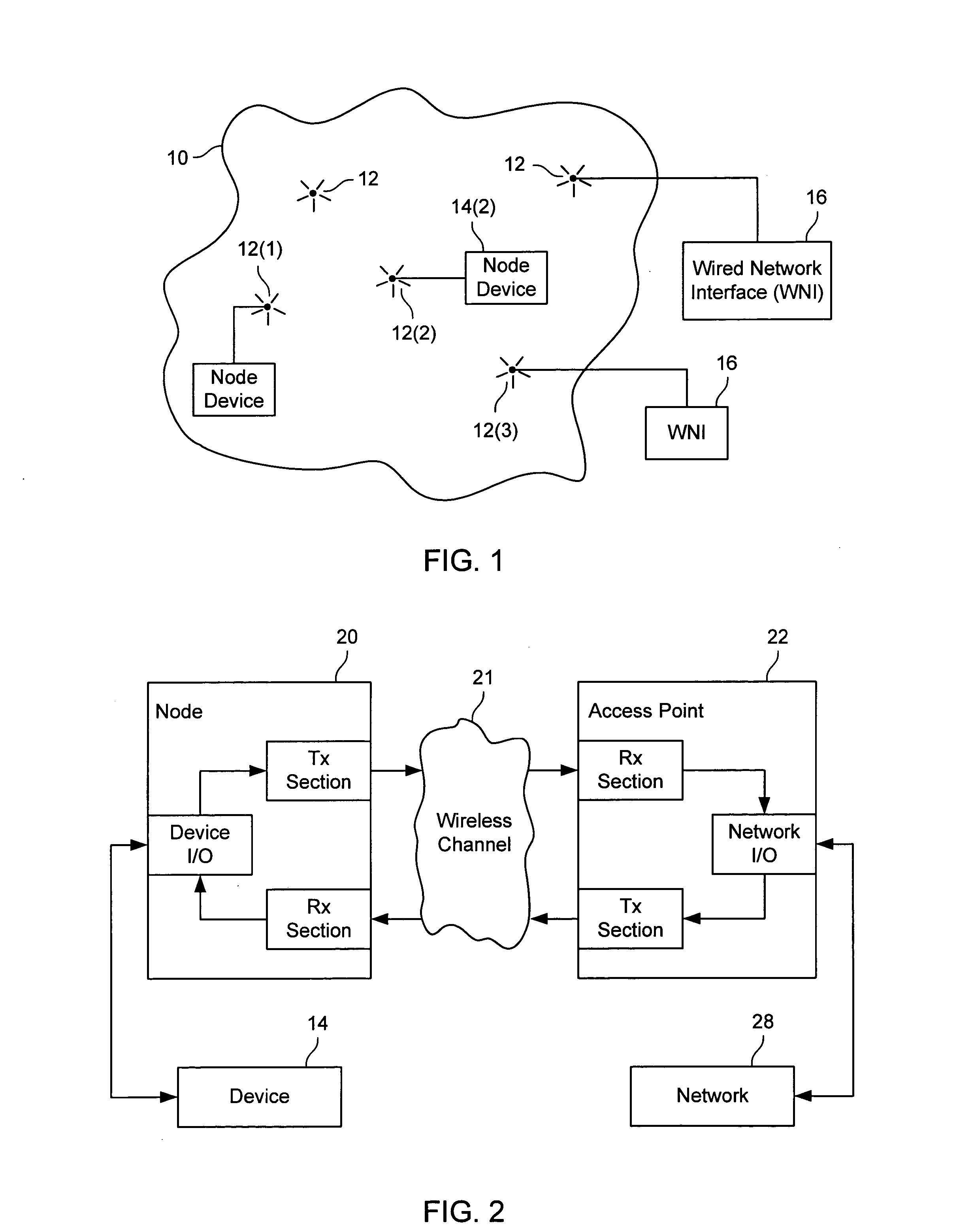
[0021]FIG. 1 illustrates a simple wireless network that might use the present invention. As shown in FIG. 1, a wireless network 10 comprises a plurality of nodes 12 wherein each node 12 is capable of communicating with at least one other node 12 of wireless network 10. In specific implementations, wireless network 10 is a local area wireless network, as might be used within a building, campus, vehicle or similar environments.

[0022] In a specific embodiment, wireless network 10 is designed to be compliant with one or more of the IEEE 802.11 standards. However, it should be understood that other standards and nonstandard networks might be substituted therefore to solve problems similar to those solved in the 802.11 environment. For example, the IEEE 802.11g standard contemplates different signals than the 802.11a or 802.11b standards and the 802.11 set of standards might be further modified for later developments. Thus, while many of the examples described herein solve the problem of...


PUM


Abstract

A packet detector joint detects 802.11a packets, 802.11b packets and interference that is within a monitored frequency range but is not formatted as 802.11a packets or 802.11b packets. The packet detector can use signals from one or more antennas. Detection of signals is done using differentially detected correlations. In addition to packet detection, the packet detector can identify signal levels, noise levels and locations of narrowband interference. The process of packet detection and identifying other indicators can be done simultaneously and as the signal is being received.

Description

BACKGROUND OF THE INVENTION [0001] Wireless networks have become increasingly popular, as computers and other devices can be coupled for data communications without requiring wired connections between the network nodes. One set of standards for wireless networks is the IEEE 802.11 standards, but other wireless standards or protocols might be used instead. In the IEEE 802.11 standards, there are at least two widely-used standards, 802.11a and 802.11b, and communication systems and devices might be required to support both standards and / or be required to operate in areas where both are being used. [0002] Interference among the two standards can be avoided, as they operate in different frequency ranges. However, recent additions such as the 802.11g standard allow for OFDM transmissions (802.11a is an OFDM transmission protocol) in the 2.4 GHz band where 802.11b direct-sequence spread-spectrum transmissions might be present. The fact that packets with different modulations can be presen...

Claims


Application Information

Patent Timeline
Patent Type & Authority Applications(United States)
IPC IPC(8): H04B17/00H04Q7/24
CPCH04B17/318
Inventor AWATER, GEERT ARNOUTGARDNER, JAMESVAN NEE, RICHARDSTEELE, GREGORY C.
Owner QUALCOMM INC
Learn More