Moving picture encoding method and decoding method

a moving picture and encoding technology, applied in the field of encoding and decoding compressed moving picture data, can solve the problems of not being able to determine whether a backward reference frame can be utilized, frame cannot adapt to direct mode, display position information may not match the time information included in a communication packet or file format actually used, etc., to achieve the effect of increasing prediction efficiency and reducing the amount of data

Active Publication Date: 2005-07-14
MAXELL HLDG LTD
View PDF22 Cites 250 Cited by
  • Summary
  • Abstract
  • Description
  • Claims
  • Application Information

AI Technical Summary

Benefits of technology

[0017] According to the present invention, a clear determination can be made as to whether the direct mode can be used or not. Further, the direct mode and its alternative mode can be used effectively, thereby increasing prediction efficiency and reducing the amount of data.

Problems solved by technology

The display position information, however, may not match time information included in a communication packet or file format actually used for display.
However, in a moving picture encoding / decoding system into which the new functions are introduced, there may be no backward reference frame used in the direct mode, or a backward reference frame set by default from multiple backward reference frames may not be a future frame.
Such a frame cannot adapt to the direct mode.
Further, if each frame is managed by numbers in decoding order, it cannot be determined whether a backward reference frame can be utilized.
Such a block cannot adapt to the direct mode.

Method used


Image

  • Moving picture encoding method and decoding method
  • Moving picture encoding method and decoding method
  • Moving picture encoding method and decoding method

Examples


embodiment 1

(EMBODIMENT 1)

[0049] An embodiment will now be described using the accompanying drawings.

[0050] A flow of processing from a frame header to macroblock data will be described in order.

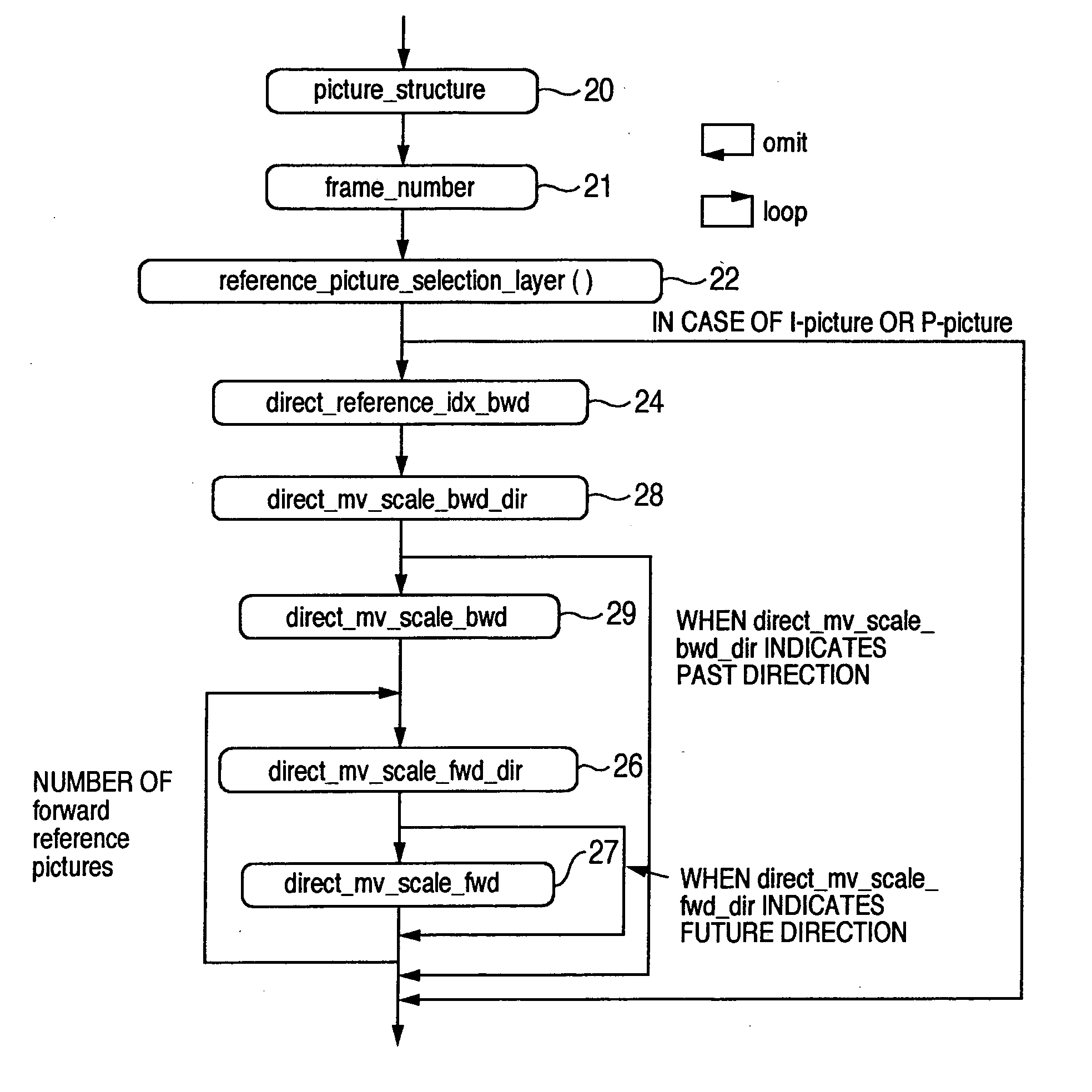
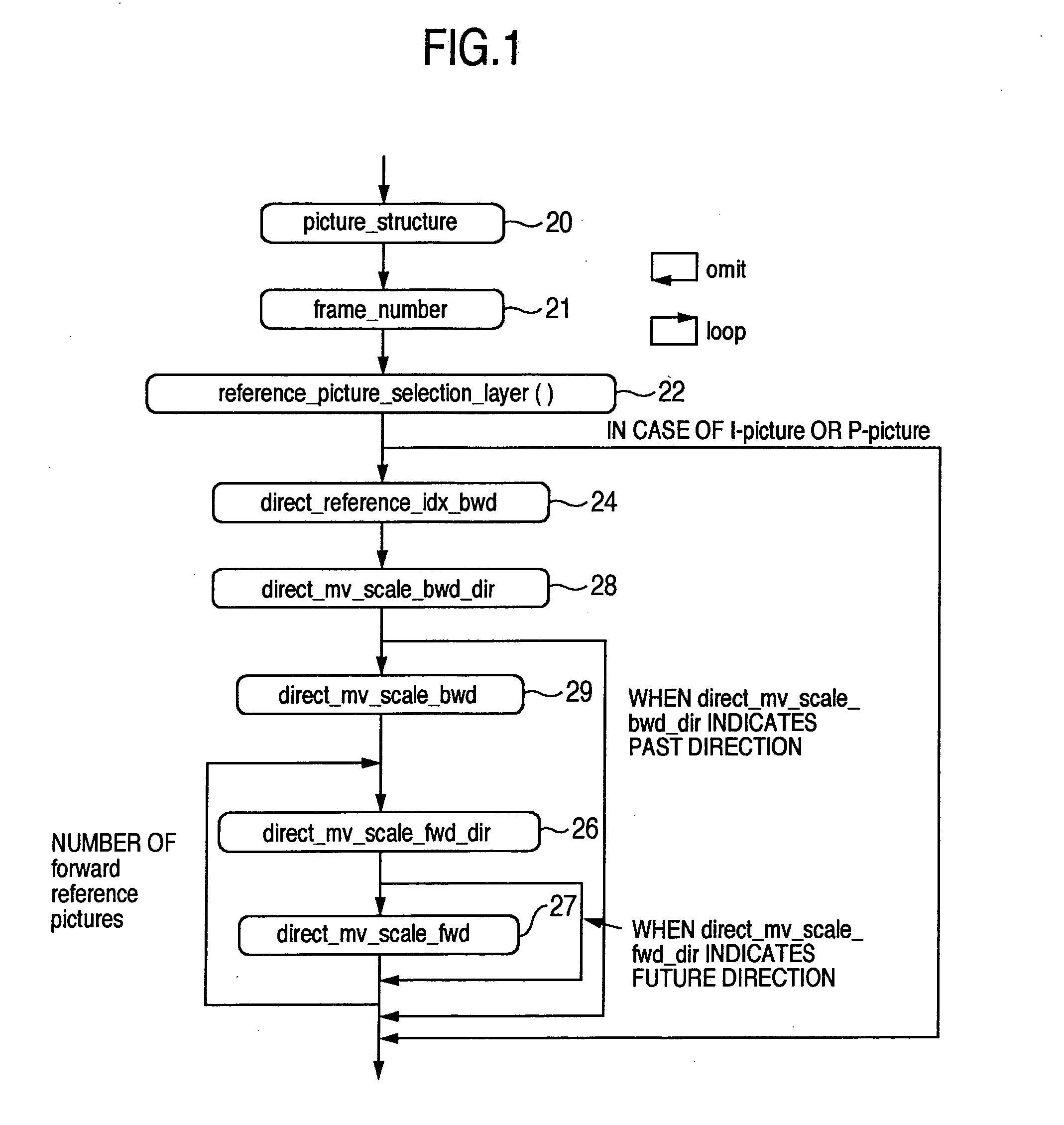
[0051]FIG. 1 shows an example of frame header information. The following shows an example of processing for decoding picture header data in C-language:

picture_layer( ){ picture_structure frame_number reference_picture_selection_layer( ) if(coding_type( )==B-picture){  direct_mv_scale_bwd_dir[index]  if(direct_mv_scale_bwd_dir[index]){ / / futuredirection    direct_mv_scale_bwd[index]   for(index=0, indexindex++){      direct_mv_scale_fwd_dir[index]      if(direct_mv_scale_fwd_dir[index]){ / / pastdirection       direct_mv_scale_fwd[index]    }  } }}

[0052] The scanning structure (frame / field) of each picture is indicated in picture_structure 20. The identification number of the frame is specified in frame_number 21. The way of assigning the frame_number is roughly divided into two types. One is a case wher...


PUM


Abstract

Conventionally there has been a case that the direct mode cannot be applied effectively depending on the block. With such being the case, information indicating whether a backward reference frame set by default can be utilized in the direct mode is provided to a decoder. A switching procedure to switch to a compensation method applicable when a collocated block has no forward motion vector for effective use, and the compensation method are also provided to the decoder. Thus, it is possible to clearly determine whether the reference frame can be used in the direct mode. Further, when the frame number has no time information, it is possible to effectively send information indicating the relationship between the reference frame and the current frame. Furthermore, the alternative mode and its switching procedure of the present invention make it possible to improve the prediction performance when the direct mode cannot be applied.

Description

TECHNICAL FIELD [0001] The present invention relates to the technology of encoding and decoding compressed moving picture data, and particularly to the technology of encoding and decoding on a block basis. BACKGROUND ART [0002] The following explains the general outlines of a moving picture encoding / decoding method for performing encoding and decoding on a block basis. [0003] As shown in FIG. 3, one frame of a moving picture consists of one luminance signal (Y signal 61) and two color difference signals (Cr signal 62 and Cb signal 63), and each color difference signal has an image size the length and width of which are one-half of those of the luminance signal, respectively. In the common video standards, each frame of a moving picture is divided into small blocks as shown in FIG. 3, and reproduction is made in units of blocks called macroblocks. FIG. 5 shows the structure of a macroblock. The macroblock consists of a Y signal block 30 of 16×16 pixels, and a Cr signal block 31 and a...

Claims


Application Information

Patent Timeline
Patent Type & Authority Applications(United States)
IPC IPC(8): H04N19/50G06T9/00H04N19/12H04N19/139H04N19/176H04N19/186H04N19/423H04N19/503H04N19/51H04N19/577H04N19/61H04N19/625
CPCH04N19/176H04N19/70H04N19/46H04N19/51H04N19/513H04N19/577H04N19/109H04N19/44H04N19/517H04N19/573H04N19/61H05K999/99
Inventor SUZUKI, YOSHINORI
Owner MAXELL HLDG LTD
Why Eureka
Try Eureka