Image encoding device, image decoding device, image encoding method, and image decoding method

a technology of image signal and encoding method, which is applied in the direction of signal generator with optical-mechanical scanning, color television with bandwidth reduction, etc., can solve the problems of deteriorating encoding efficiency and insufficient prediction efficiency, and achieve the improvement of encoding efficiency and accuracy of image signal in frame in the related ar

Active Publication Date: 2012-11-29
ADVANCED CODING TECH LLC
View PDF7 Cites 19 Cited by
  • Summary
  • Abstract
  • Description
  • Claims
  • Application Information

AI Technical Summary

Benefits of technology

[0029]In the image encoding device, the image decoding device, the image encoding method, and the image decoding method according to the present invention, a reference image vertically or horizontally inversed with respect to the encoded decoding image, which is used as the template signal for predicting the texture component, is generated and used as the prediction image, such that the precision of the image signal in the frame in the related art can be improved. A pre

Problems solved by technology

In the case where a prediction image having a high correlation over a decode amount of transmitting the disparity vector may be generated, high encoding efficiency can be implemented with respect to the intra-prediction, but in the case where a transmission quantity of the disparity

Method used


Image

  • Image encoding device, image decoding device, image encoding method, and image decoding method
  • Image encoding device, image decoding device, image encoding method, and image decoding method
  • Image encoding device, image decoding device, image encoding method, and image decoding method

Examples


first embodiment

[0053]First, forms of an image encoding device and an image decoding device according to a first embodiment of the present invention will be described.

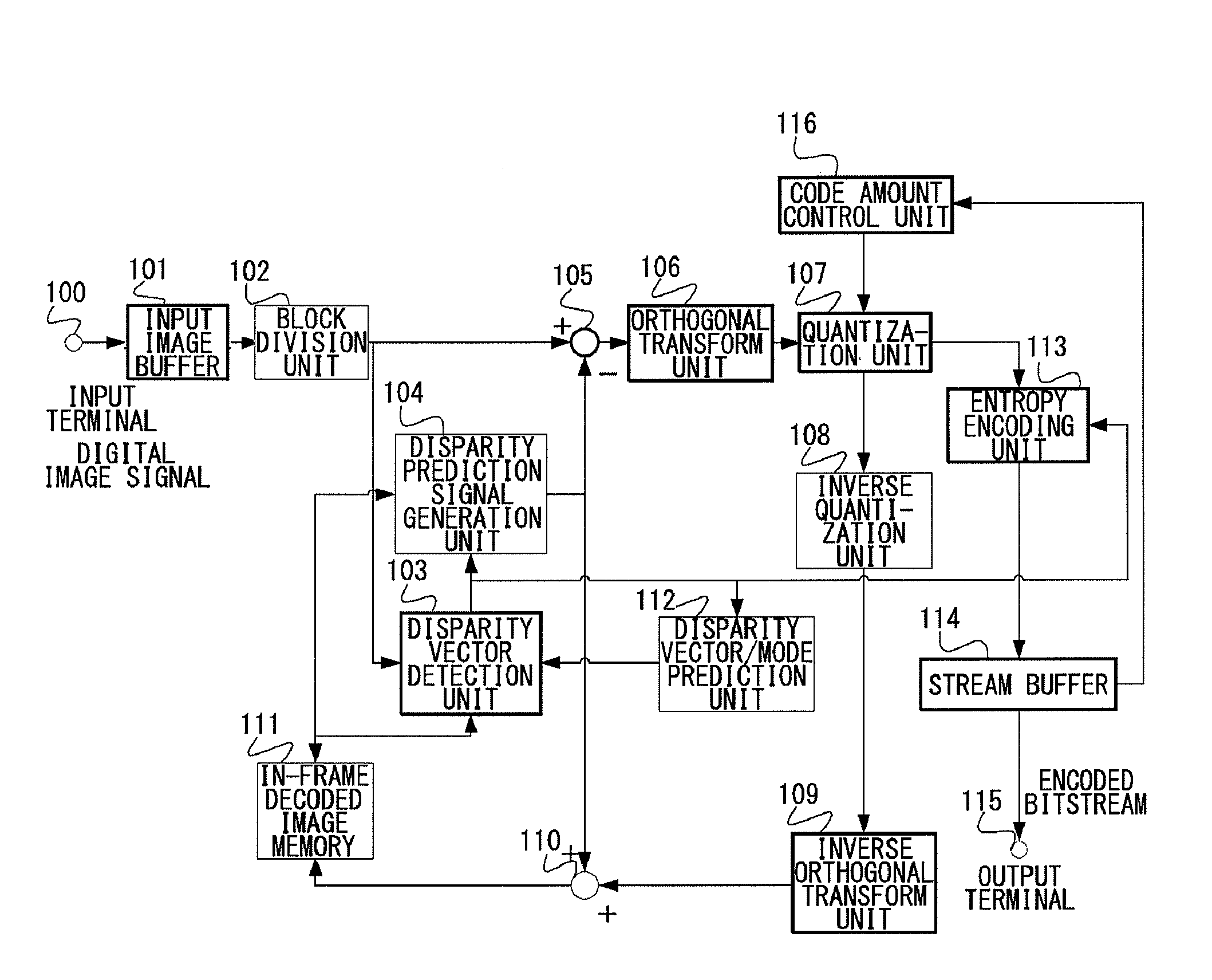
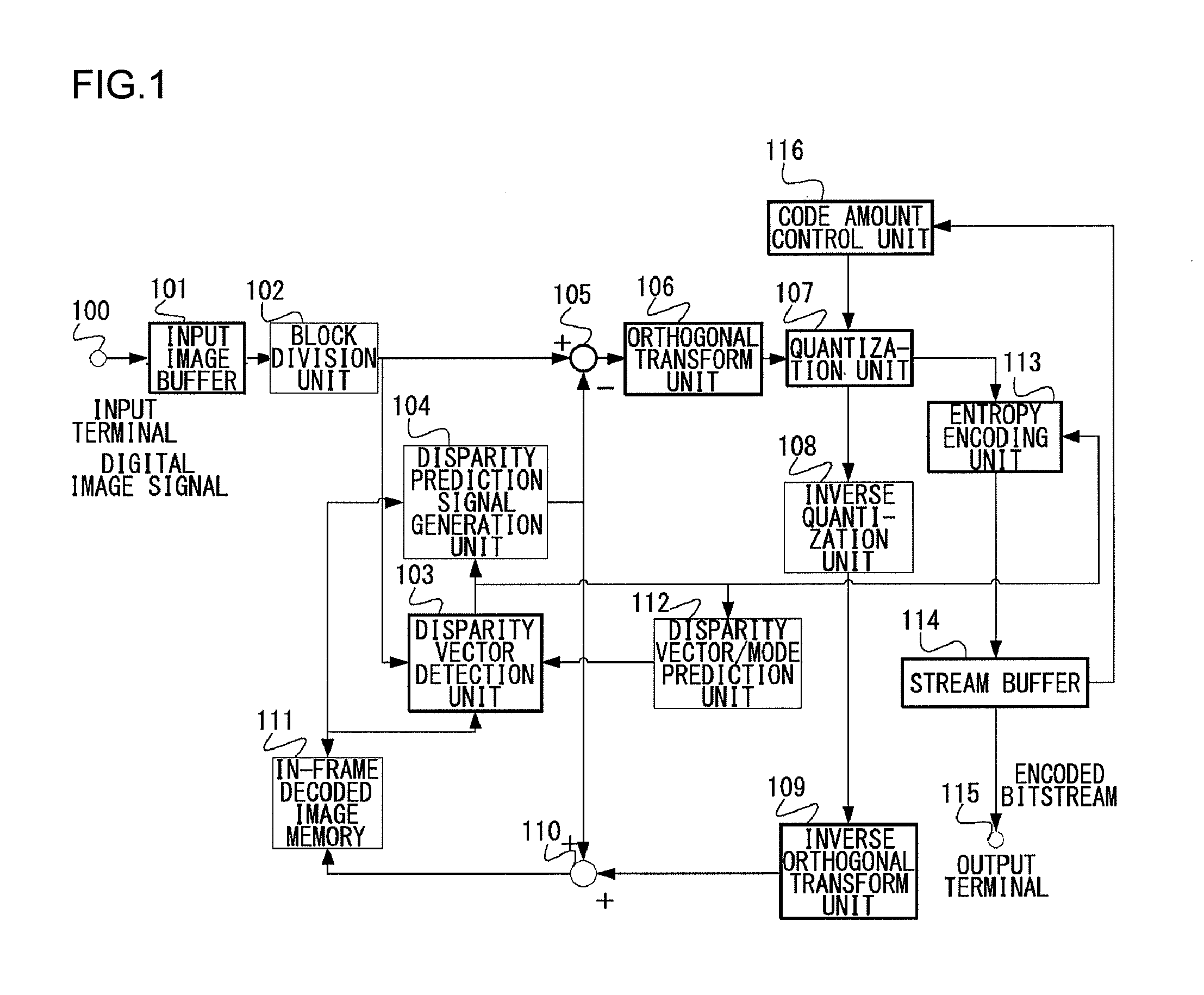
[0054]FIG. 1 is a configuration diagram illustrating a form of an image encoding device according to a first embodiment of the present invention. As illustrated in FIG. 1, the image encoding device according to the embodiment includes an input terminal 100, an input image buffer 101, a block division unit 102, a disparity vector detection unit 103, a disparity prediction signal generation unit 104, a subtractor 105, an orthogonal transform unit 106, a quantization unit 107, an inverse quantization unit 108, an inverse orthogonal transform unit 109, an adder 110, an in-frame decoded image memory 111, a disparity vector / mode prediction unit 112, an entropy encoding unit 113, a stream buffer 114, an output terminal 115, and a code amount control unit 116.

[0055]The disparity vector detection unit 103, the disparity prediction signal gener...

second embodiment

[0115]Subsequently, forms of an image encoding device and an image decoding device according to a second embodiment of the present invention will be described. The first embodiment is the embodiment of the image encoding / decoding device using only the correlation in the frame, but the second embodiment is an embodiment of the image encoding / decoding device capable of using a temporal correlation of a moving image, which uses a correlation in the frame and a correlation between the frames.

[0116]FIG. 7 is a configuration diagram illustrating the form of the image encoding device according to the second embodiment of the present invention. As illustrated in FIG. 7, the image encoding device according to the embodiment includes the input terminal 100, the input image buffer 101, the block division unit 102, the subtractor 105, the orthogonal transform unit 106, the quantization unit 107, the inverse quantization unit 108, the inverse orthogonal transform unit 109, the adder 110, the in-...

third embodiment

[0159]Subsequently, forms of an image encoding device and an image decoding device according to a third embodiment of the present invention will be described. The third embodiment is an embodiment in which a function of calculating the disparity vector by using the adjacent image of the encoding target block, which is presented in Japanese Patent Application Laid-Open No. 2007-043651 as the template is added in the configuration of the second embodiment, and a block in which the reference image is vertically and horizontally inverted is provided as a prediction target signal with respect to a vector calculation function, which is a feature of the present invention.

[0160]FIG. 12 is a configuration diagram of the image encoding device according to the third embodiment and FIG. 13 is a configuration diagram of the image decoding device according to the third embodiment, and operations thereof. will be described.

[0161]As illustrated in FIG. 12, the image encoding device according to the...


PUM


Abstract

A disparity vector detection unit retrieves a signal having a high correlation with an encoding target block and acquire the signal having the high correlation and a disparity vector which is a disparity in a screen of the encoding target block by using a local decoded image of a block in the same image signal which was previously encoded, with respect to the encoding target block. A disparity prediction signal generation unit generates a prediction signal in accordance with the disparity vector. The disparity vector detection unit includes a DC calculation unit operative to predict a DC component of an image signal of the encoding target block from a neighboring decoded image, and a disparity reference DC calculation unit operative to calculate a DC component of a prediction signal represented by the disparity vector.

Description

BACKGROUND OF THE INVENTION[0001]1. Field of the Invention[0002]The present invention relates to a technique for encoding and decoding an image signal, and more particularly, to an image encoding device, an image decoding device, an encoding method, and an image decoding method using a prediction processing in a screen which generates a prediction signal for an image signal as a target from an encoded image and encodes a differential signal with the prediction signal.[0003]2. Description of the Related Art[0004]In recent years, a service of delivering digitalized image and voice contents via a broadcast wave of a satellite or ground wave or a network has been put to practical use and high-efficiency encoding for efficiently recording information of an image and voice having a large amount of information has bee required. With high definition and diversification of contents, the number of images and the amount of data which are encoded have been further increased and high-efficiency ...

Claims


Application Information

Patent Timeline
IPC IPC(8): H04N7/32H04N19/50H04N19/103H04N19/134H04N19/136H04N19/137H04N19/139H04N19/152H04N19/196H04N19/423H04N19/46H04N19/503H04N19/513H04N19/57H04N19/593H04N19/61H04N19/625H04N19/70H04N19/80H04N19/91
CPCH04N19/197H04N19/105H04N19/52H04N19/176H04N19/88H04N19/51H04N19/61H04N19/593H04N19/46
Inventor UEDA, MOTOHARU
Owner ADVANCED CODING TECH LLC
Why Eureka
Try Eureka