Reconfigurable computer tomography scanner

a computer tomography and reconfigurable technology, applied in tomography, applications, instruments, etc., can solve the problem that large scanners are not particularly suited to scanning parts of the body

Active Publication Date: 2005-07-14
XORAN TECH
View PDF17 Cites 16 Cited by
  • Summary
  • Abstract
  • Description
  • Claims
  • Application Information

AI Technical Summary

Problems solved by technology

Thus, the large scanners are not particularly suited for scanning part of a body, such as the patient's head or extremities.

Method used


Image

  • Reconfigurable computer tomography scanner
  • Reconfigurable computer tomography scanner
  • Reconfigurable computer tomography scanner

Examples


Embodiment Construction

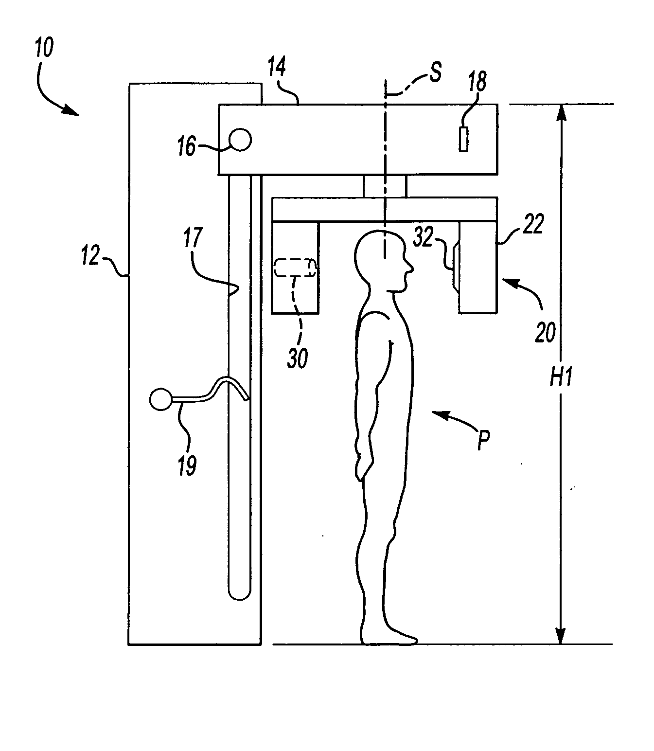
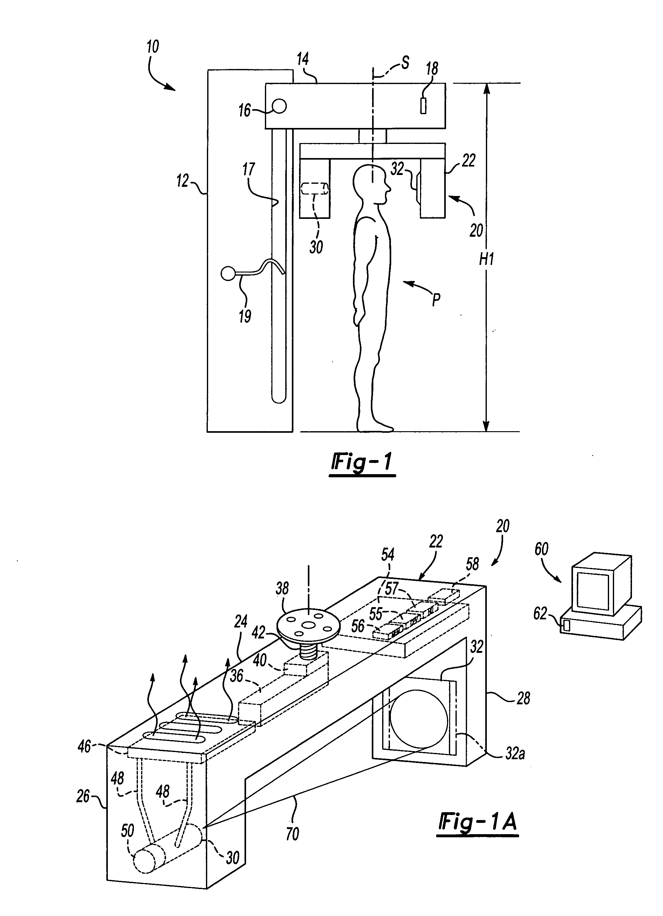
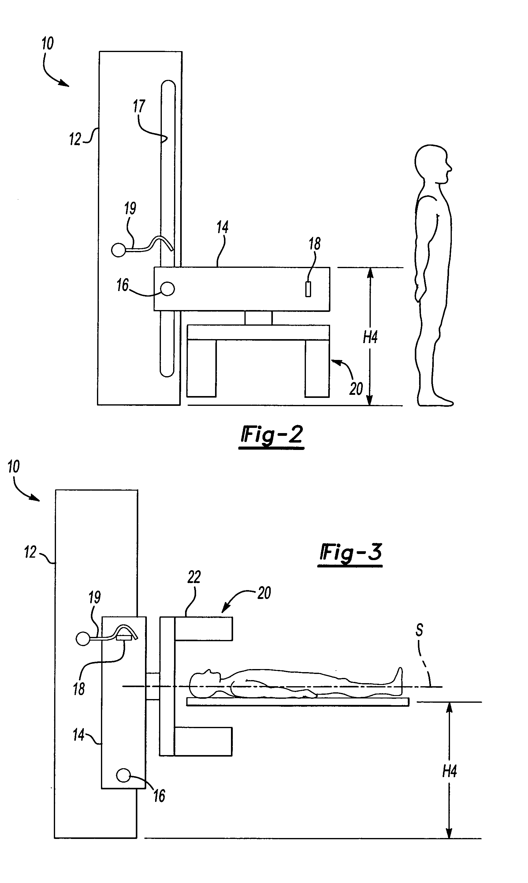
[0017] A CT scanner system 10 according to a first embodiment of the present invention is shown schematically in FIG. 1. The system 10 includes a generally vertical frame 12 on which is mounted a support 14. A pivot axis 16 at one end of the support 14 is pivotably and slidably mounted in a track 17 in the frame 12. The support 14 includes a first latch member 18 at an opposite end of the support 14. The frame 12 includes a complementary second latch member 19 at a mid-point along the track 17.

[0018] A CT scanner 20 is mounted to the support 14. The CT scanner 20 includes a gantry 22, which rotatable about a scan axis S. In FIG. 1, the scan axis S is vertical. The CT scanner 20 generally includes an x-ray source 30 opposite an x-ray detector 32, with the scan axis S between the x-ray source 30 and x-ray detector 32.

[0019] The CT scanner 20 is shown in more detail in FIG. 1A. In the CT scanner 20, all of the scanner components are contained in a gantry 22. The gantry 22 provides th...


PUM

PropertyMeasurementUnit
CTaaaaaaaaaa
rotationaaaaaaaaaa
poweraaaaaaaaaa

Abstract

A CT scanner is reconfigurable to multiple orientations and positions. The scanner includes a gantry on which the x-ray source and x-ray detector are mounted. The gantry is mounted on a support and is rotatable about a scan axis relative to the support. The support is movable and / or pivotable relative to a frame, such that the scan axis can be vertical or horizontal.

Description

[0001] This application claims priority to U.S. Provisional Application Ser. No. 60 / 535,177, filed Jan. 8, 2004.BACKGROUND OF THE INVENTION [0002] The present invention relates generally to computer tomography (CT) scanners and more particularly to a compact, reconfigurable CT scanner. Generally, computer tomography scanners are large enough to scan a patient's entire body. Typically, an x-ray source is mounted on a movable ring, which also includes an array of x-ray detectors opposite the x-ray source. The patient lies on a platform that moves through the ring. The ring is rotated so the x-ray source and detectors revolve around the patient, while the patient is moved through the ring on the platform. The x-ray slices through the body by taking a series of x-rays in a spiral pattern. The x-ray source is typically a “fan beam” x-ray source, i.e., it sends a fan-shaped beam that defines a single plane through the body and is received by the detectors. [0003] These scanners are very l...

Claims


Application Information

Patent Timeline
Patent Type & Authority Applications(United States)
IPC IPC(8): A61B6/00A61B6/03
CPCA61B6/035A61B6/501A61B6/4488
Inventor SUKOVIC, PREDRAGRAKIC, MIODRAG
Owner XORAN TECH
Why Eureka
Try Eureka