Apparatus and method for controlling power save mode of an electronic appliance

a technology of electronic appliances and apparatus, which is applied in the direction of sustainable buildings, liquid/fluent solid measurements, instruments, etc., can solve the problems of wasting electricity, wasting a considerable amount of time heating up electronic appliances, and generally taking a long time to heat or cool down fixing units, so as to prevent electricity from being wasted and maximize the convenience of users

Inactive Publication Date: 2005-07-14
SAMSUNG ELECTRONICS CO LTD
View PDF7 Cites 14 Cited by
  • Summary
  • Abstract
  • Description
  • Claims
  • Application Information

AI Technical Summary

Benefits of technology

[0019] The present invention provides an apparatus and method of controlling a power save mode of an electronic appliance, which can maximize the convenience for users when the electronic appliance is frequently...

Problems solved by technology

However, if power is continuously supplied to the electronic appliance even after the electronic appliance stops performing its operations, the electronic appliance may waste energy.
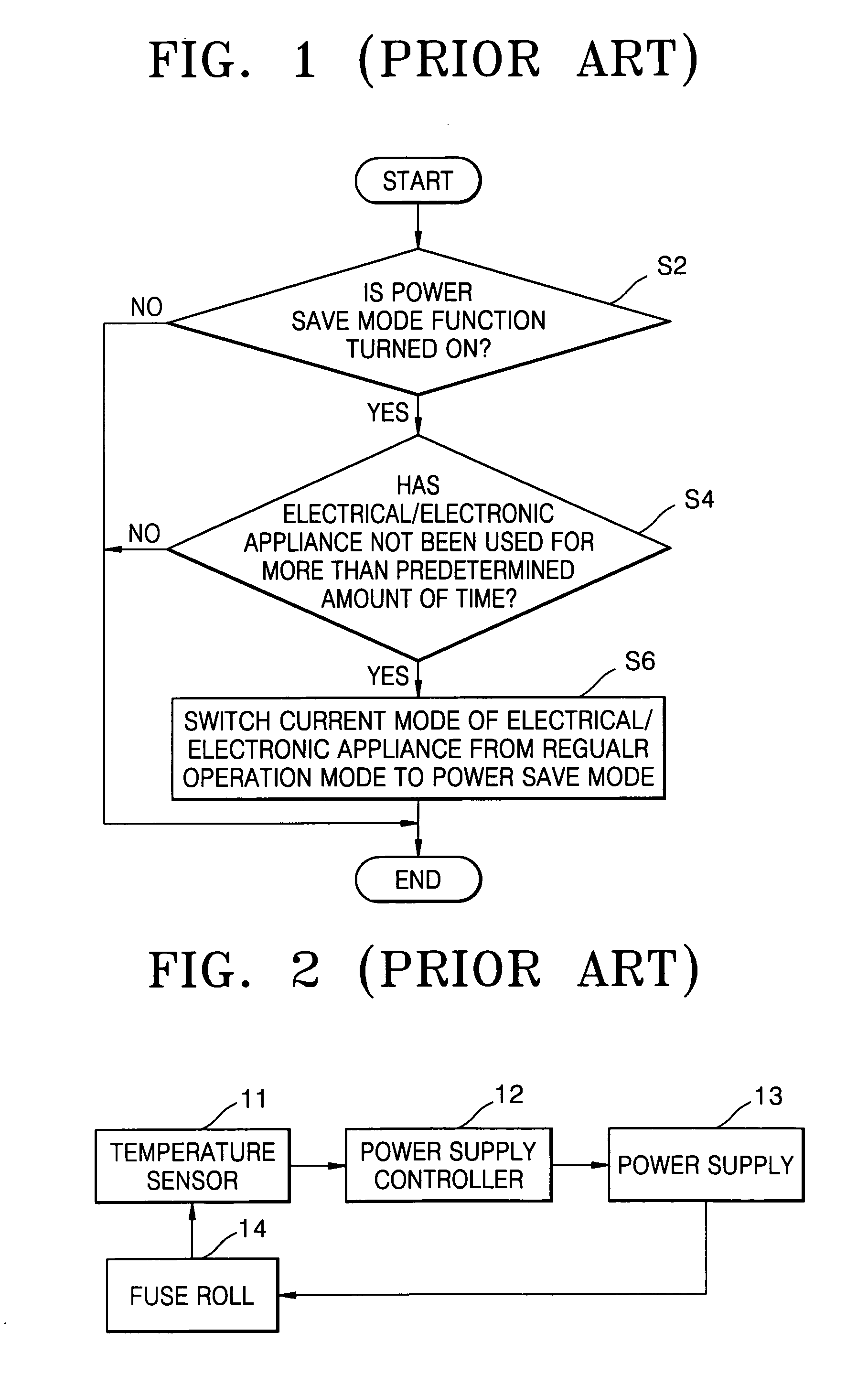
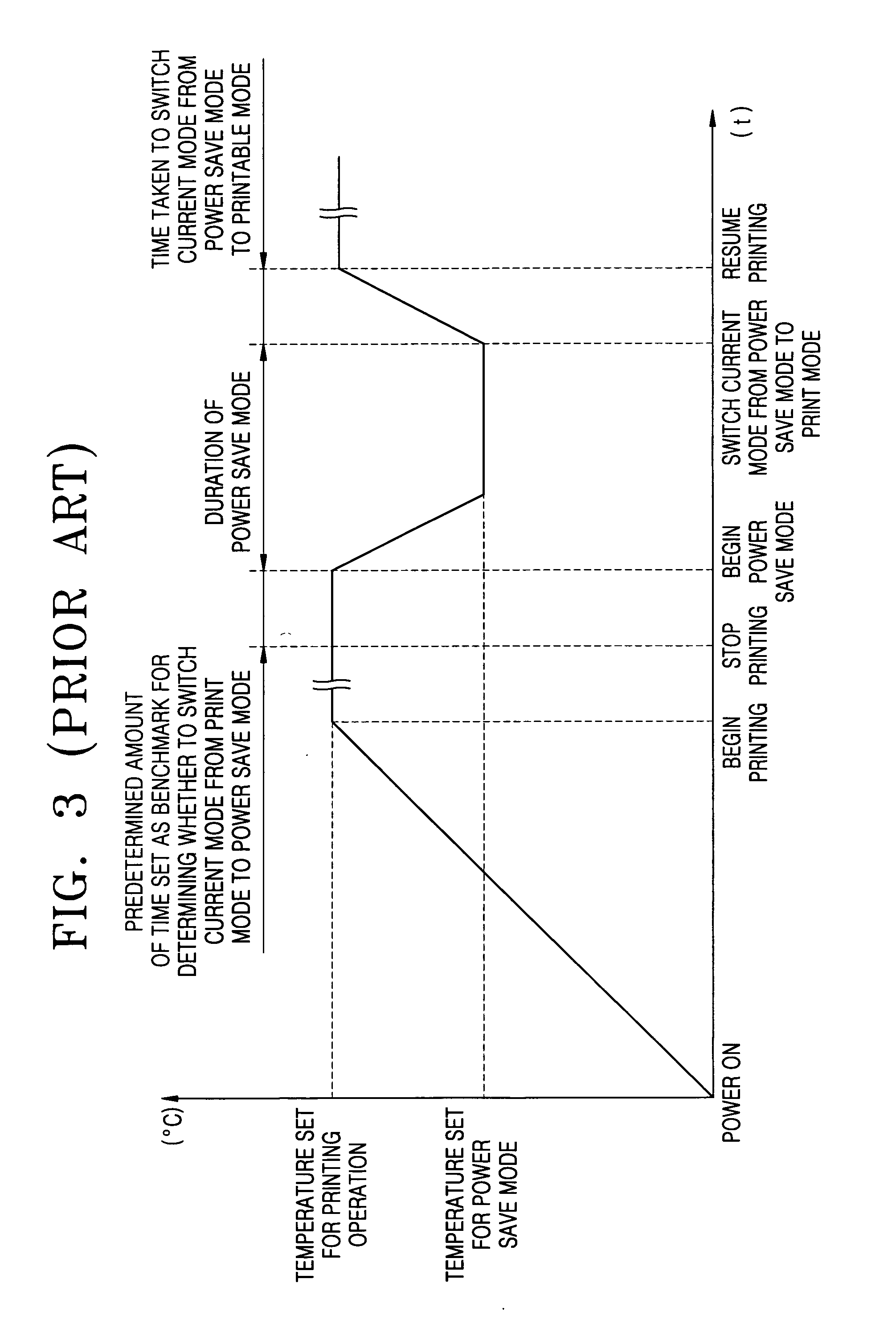
Even though the conventional power supply controlling apparatus can reduce the power consumption of the electronic appliance to some extent, it spends a considerable amount of time warming the electronic appliance up, for instance, when switching the current mode of the electronic appliance from a power save mode to an operation mode or vice versa.
For example, a fixing unit for a color laser printer, which fixes a toner image transferred onto a recording medium, such as printing paper or the like, operates at a high temperature, and it generally takes a long time to heat the fixing unit or cool it down.
Accordingly, it also takes a long time to switch the current mode of the color laser printer from a power save mode to an operation mode, to allow the toner image to be fixed onto the recording medium.
Therefore, a user has to wait for a long time period until the current mode o...

Method used


Image

  • Apparatus and method for controlling power save mode of an electronic appliance
  • Apparatus and method for controlling power save mode of an electronic appliance
  • Apparatus and method for controlling power save mode of an electronic appliance

Examples


Embodiment Construction

[0035] The present invention will now be described more fully with reference to the accompanying drawings, in which exemplary embodiments of the invention are shown. The matters defined in the following description such as a detailed construction and elements are provided to assist in a comprehensive understanding of the invention. Those of ordinary skill in the art will appreciate that various changes and modifications can be made to the embodiments described herein without departing form the spirit and scope of the invention. Also, descriptions of well-known functions or constructions are omitted for the sake of clarity

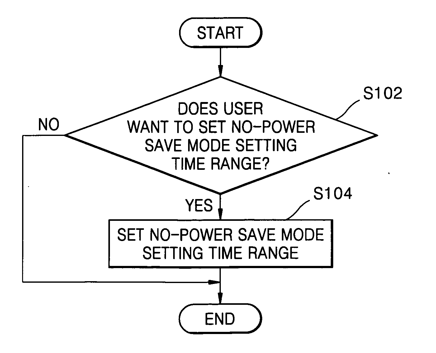
[0036]FIG. 4 is a block diagram illustrating an apparatus for controlling a power save mode of an electronic appliance according to an exemplary embodiment of the present invention. Referring to FIG. 4, the apparatus comprises a power save mode control unit 110, which prevents a power save mode from being set in a predetermined time range (hereinafter, referred to ...


PUM


Abstract

An apparatus and method for controlling a power save mode of an electronic appliance, such as a printer, a photocopier, a multifunctional device, or an electronic oven, are provided. The apparatus comprises a power save mode control unit, which prevents a power save mode from being set in the electronic appliance during a predetermined time range. The apparatus may further comprise a no-power save mode setting time range setting unit, which sets the predetermined time range so that the power save mode can be prevented from being set in the electronic appliance.

Description

CROSS-REFERENCE TO RELATED APPLICATIONS [0001] This application claims the benefit under 35 U.S.C. §119(a) of Korean Patent Application No. 10-2004-0001418, filed on Jan. 9, 2004, in the Korean Intellectual Property Office, the entire disclosure of which is hereby incorporated herein by reference. BACKGROUND OF THE INVENTION [0002] 1. Field of the Invention [0003] The present invention relates to an apparatus and method for controlling a power save mode of an electronic appliance, such as a printer, a photocopier, or an electronic oven. More particularly, the present invention relates to an apparatus and method for controlling a power save mode of an electronic appliance, which can maximize user convenience when the electronic appliance is frequently used, and can prevent the waste of electricity when the electronic appliance is not used by setting a power save mode in the electronic appliance at all times when the electronic appliance is not frequently used. [0004] 2. Description o...

Claims


Application Information

Patent Timeline
IPC IPC(8): B41J29/38G03G21/14G06F1/26G06F1/32
CPCG06F1/3203Y02B60/1267G06F1/3284Y02D10/00D05C1/02D05C9/00
Inventor KIM, HYUCK
Owner SAMSUNG ELECTRONICS CO LTD
Why Eureka
Try Eureka