
Laminar flow lighted waterfall apparatus for spa

a waterfall and laminar flow technology, applied in lighting applications, lighting and heating apparatus, light source combinations, etc., can solve the problems of inability to adapt waterfall structures to portable spas, inability to use high-pressure pumping power in in-ground pools, and turbulent water flow

Active Publication Date: 2005-07-21
WATKINS MFG
View PDF14 Cites 23 Cited by
  • Summary
  • Abstract
  • Description
  • Claims
  • Application Information

AI Technical Summary

Benefits of technology

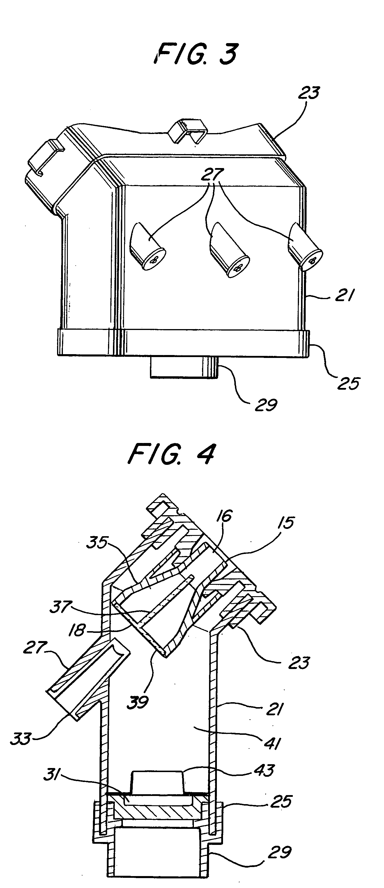
[0005] A plenum chamber is constantly being filled with water at one end and ejecting a laminar stream of water at another end. Light of different colors may be injected into the laminar stream, causing it to change colors as desired. The laminar stream is created by a venturi nozzle in combination with a plenum chamber, with the venturi nozzle intake end in the plenum chamber. The intake end is covered with a sieve having many small holes. A flow divider in the venturi nozzle extends from the intake end to the outlet end, helping to create a laminar stream of water at the outlet end of the nozzle. A multi-color light source encased in a clear plastic rod is pointed into the water flow at the sieve intake of the venturi nozzle. The flow divider in the nozzle carries the light through the venturi nozzle body and emits it at the nozzle restriction. An escutcheon plate that fits over the outlet end of the venturi nozzle causes a small amount of air to be injected into the laminar flow stream as it exits the nozzle to cause some light carried by the flow stream to be deflected out of the stream.

Problems solved by technology

However, regardless of the form of the waterfall, the water flow is turbulent and driven by high pressure pump equipment.
Such waterfall structures are not well adapted for use in portable spas for, among other reasons, the high pressure pumping power available in an in-ground pool is not available in a portable spa.
As a result, waterfall structures utilized in spas tend to be merely trickles of water.
The resulting waterfall effect is found lacking.

Method used


Image

  • Laminar flow lighted waterfall apparatus for spa
  • Laminar flow lighted waterfall apparatus for spa
  • Laminar flow lighted waterfall apparatus for spa

Examples


Embodiment Construction

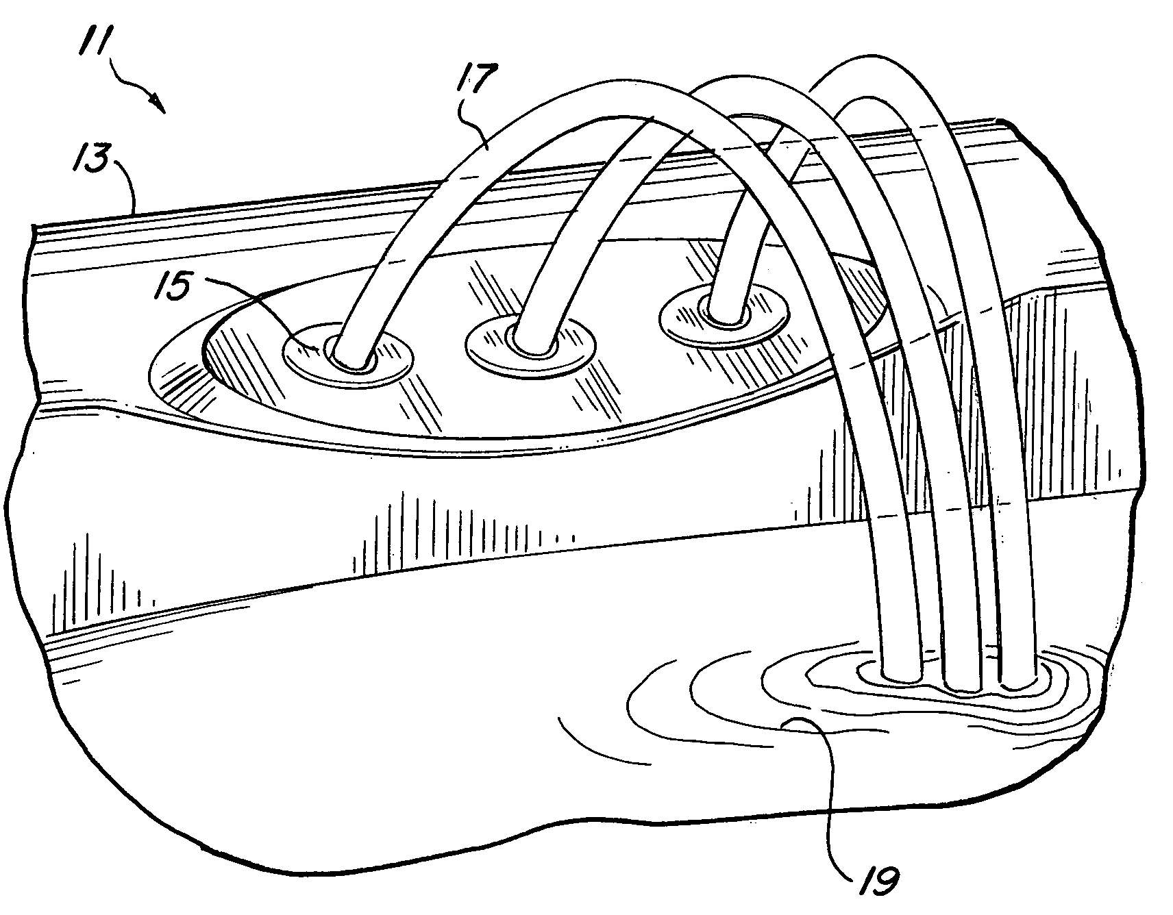
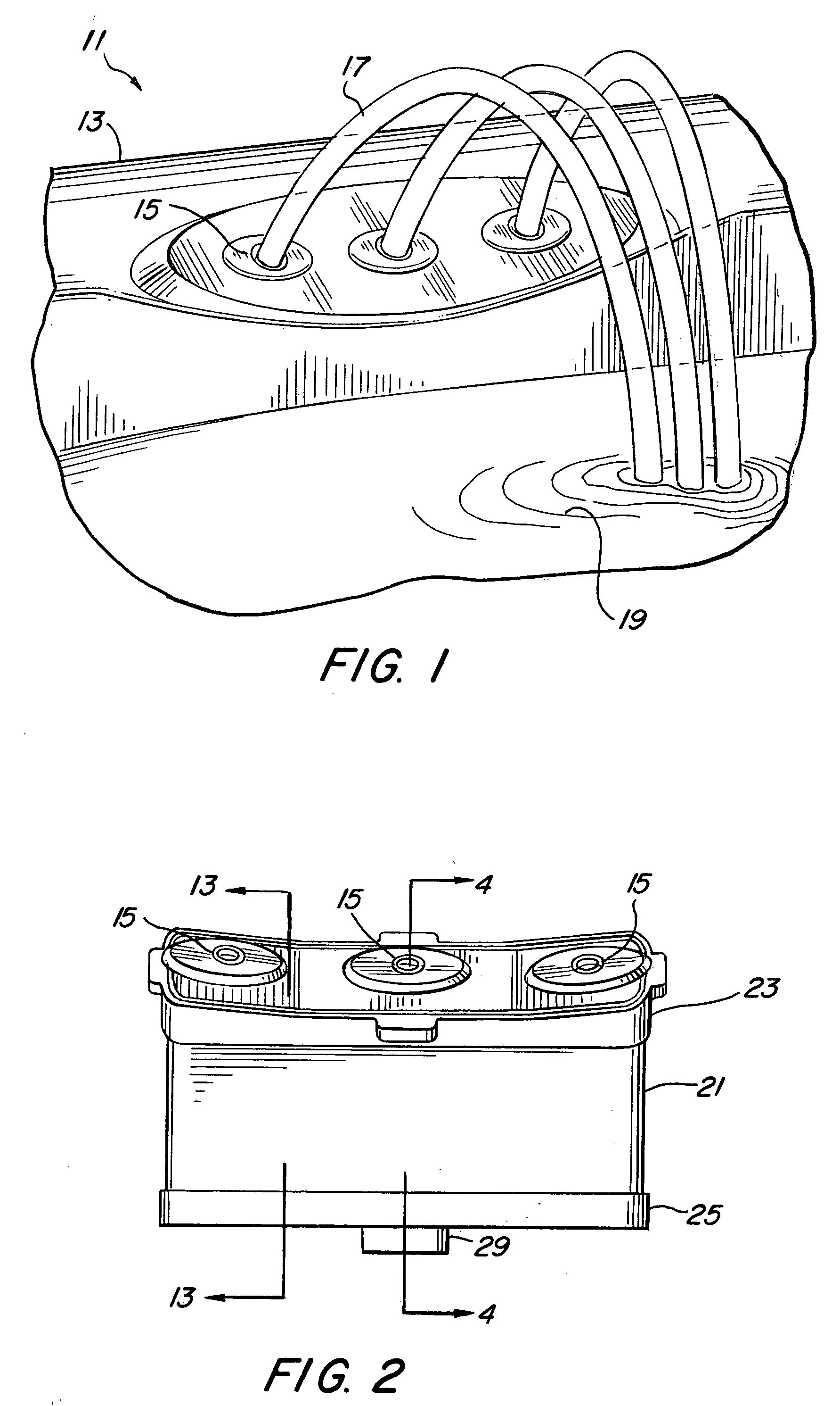
[0028]FIG. 1 illustrates a preferred installation 11 of the waterfall apparatus of the present invention in a three stream configuration which utilizes a plurality of nozzles 15 mounted within the top side 13 of a spa wall. The nozzles 15 are mounted at an incline to cause the streams of water 17 exiting from the nozzles to fall into a main body of water 19 contained in the spa.

[0029] As will be explained in further detail hereinafter, each stream of water 17 exiting its nozzle 15 is laminar flow as distinguished from turbulent flow. The laminar flow water steam 17 is lit up and carries light like a light conduit, until the stream 17 hits the main body of water 19. Upon hitting the main body of water 19, the light within the laminar flow stream scatters, creating a desirable, pleasing and relaxing effect.

[0030]FIG. 2 is a perspective illustration of the waterfall stream generating apparatus according to a preferred embodiment of the present invention. The apparatus includes a plen...


PUM


Abstract

A laminar flow waterfall in the form of a single or multiple streams of water, each exiting from a nozzle in the top edge of a spa. The laminar water stream is created by a venturi nozzle located in a plenum chamber. The inlet side of the nozzle has a cover with a plurality of small holes forcing the water flow to enter the nozzle as laminar flow. A flow divider inside the venturi nozzle, from the inlet to the restriction of the nozzle, maintains the flow laminar through the nozzle. Light is injected into the flow divider at the inlet and is carried by the flow divider to be injected into the water flow at the restriction of the nozzle.

Description

BACKGROUND OF THE INVENTION [0001] 1. Field of the Invention [0002] The present invention relates generally to improvements in spas or hot tubs, and more particularly, pertains to a new and improved waterfall apparatus in a spa. [0003] 2. Description of Related Art [0004] Waterfall structures are common in in-ground pool installations. These waterfall structures can take many shapes, providing different cascading water configurations such as sheet, falls, streams, tumbling waters, jets, for example. However, regardless of the form of the waterfall, the water flow is turbulent and driven by high pressure pump equipment. Such waterfall structures are not well adapted for use in portable spas for, among other reasons, the high pressure pumping power available in an in-ground pool is not available in a portable spa. Most of the pumping power in a portable spa is reserved for the generation of the waterjets in the spa itself. As a result, waterfall structures utilized in spas tend to be ...

Claims


Application Information

Patent Timeline
IPC IPC(8): A61H9/00E04H4/00F21S8/00
CPCA61H9/00E04H4/14E04H4/148F21Y2113/00F21W2121/02F21W2131/401F21S8/00
Inventor MCDONALD, CHRIS H.GASTINEAU, DOUGLAS R.KUNKEL, RICHARDCHILDERSTON, LARRY
Owner WATKINS MFG
Learn More