
Pipetting device with a displacement device and a drive device releasably connected therewith

a technology of displacement device and pipetting device, which is applied in the direction of sampling, laboratory glassware, instruments, etc., can solve the problems of difficult or impossible removal of pipette tip from the attachment, contamination of displacement device, time-consuming, etc., and achieves the facilitation of connection position and displacement device separation, and facilitates manufacturing, assembly and disassembly.

Active Publication Date: 2005-07-21
EPPENDORF SE
View PDF7 Cites 61 Cited by
  • Summary
  • Abstract
  • Description
  • Claims
  • Application Information

AI Technical Summary

Benefits of technology

[0013] The displacement device and the drive device of the pipetting device can be easily connected to one another by being pushed together along a longitudinal axis of the bayonet connection and rotating about the longitudinal axis of the bayonet connection and can be separated from one another in the reverse manner. When establishing the bayonet connection the cooperation between the drive member and the displaceable limiter is simultaneously produced without it requiring further particular actions therefor. When releasing the bayonet connection, the cooperation is released without particular further actions. The invention allows a particularly simple, rapid and secure connection and separation of the displacement device and the drive device, for example during assembly, before autoclaving or other cleaning of the lower part, before exchanging the lower part for the purpose of altering the working area, repairs, etc. The bayonet connection is not particularly susceptible to faults. These advantages are in particular effective when manually and automatically connecting and separating the displacement device and the drive device. The latter, for example, with automatic assembly or a workstation with automatic tool exchange.
[0020] According to an embodiment, the annular groove has a limiting wall extending in a ramp-like manner, of which the distance from the aperture increases with increasing distance from the longitudinal groove. The ramp-like path of the limiting wall facilitates finding the connection position and the separation of the displacement device from the drive device.

Problems solved by technology

Even with one-channel systems, ie pipetting devices which comprise a single attachment for a single pipette tip, this can make ejecting the pipette tip from the attachment difficult or impossible.
Air cushion pipettes can lead to contamination of the displacement device.
Penetration of fluid due to improper handling or the rising of vapour or tiny droplets of the liquid to be pipetted into the displacement device can result therefrom.
The fastening is nevertheless laborious, time-consuming and susceptible to faults.

Method used


Image

  • Pipetting device with a displacement device and a drive device releasably connected therewith
  • Pipetting device with a displacement device and a drive device releasably connected therewith

Examples


Embodiment Construction

[0036] While this invention may be embodied in many different forms, there are described in detail herein a specific preferred embodiment of the invention. This description is an exemplification of the principles of the invention and is not intended to limit the invention to the particular embodiment illustrated

[0037] The terms ‘above’, ‘below’, ‘horizontally’ and ‘vertically’ refer to the alignment of the pipetting device according to the drawings. In this connection it refers to an alignment of the pipetting device in which the pipette tip is arranged with its tip orifice below, in order to draw in liquid from a container located below the pipetting device and to dispense it into such a container.

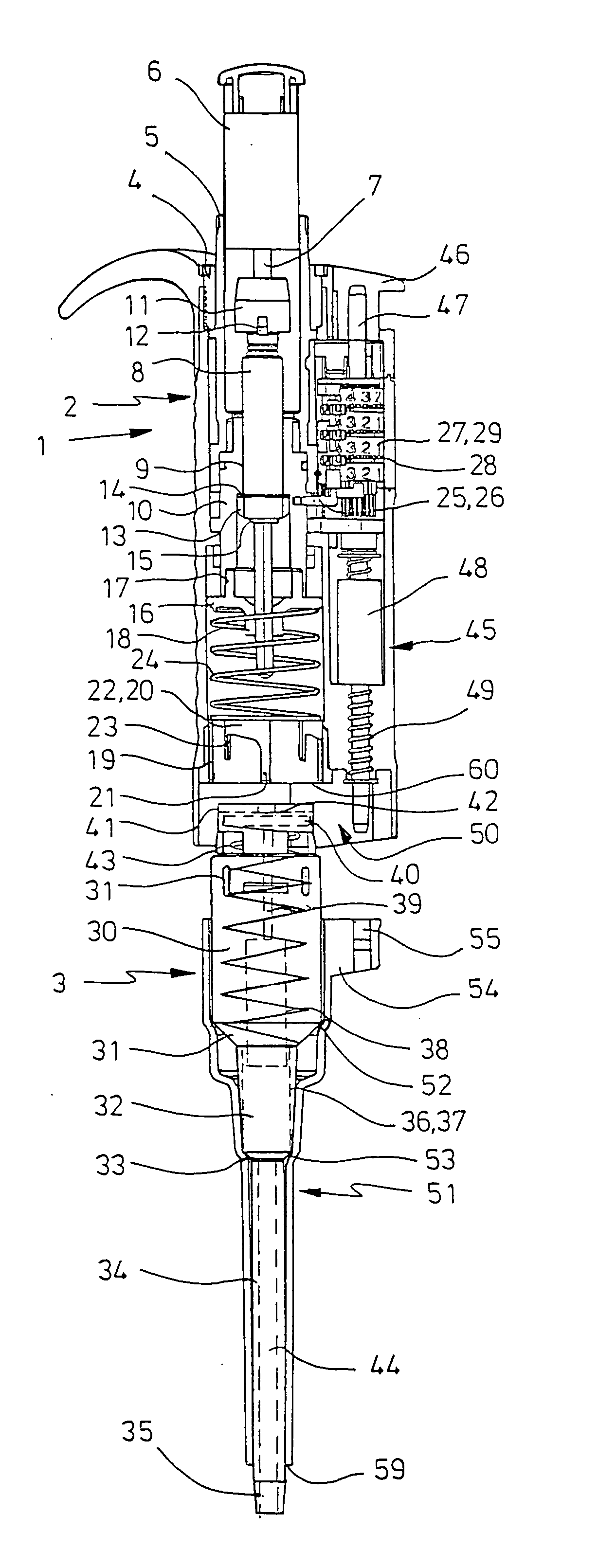
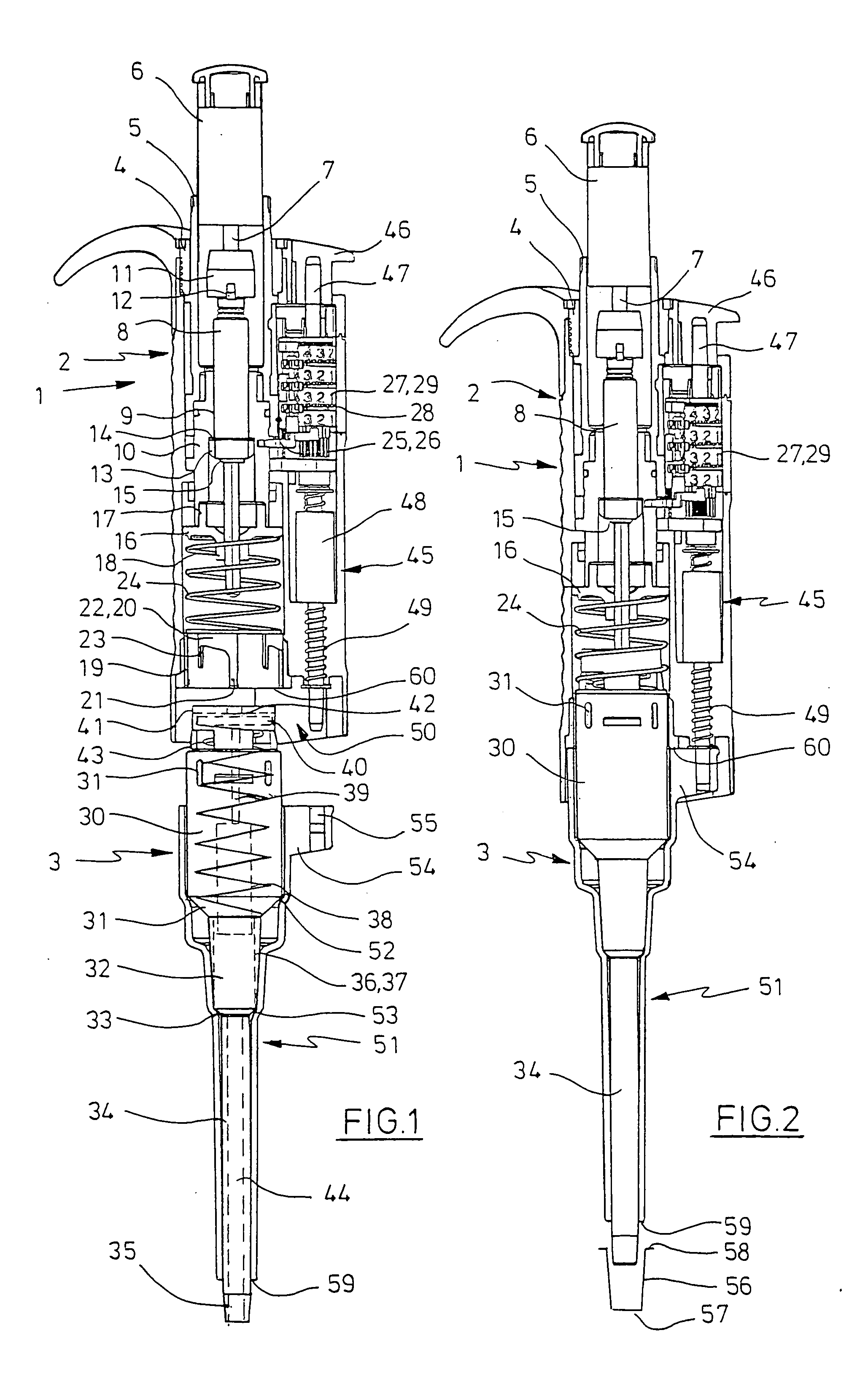
[0038] The pipetting device according to FIGS. 1 and 2 has an elongate housing 1 formed as a grip with a housing upper part 2 and a housing lower part 3. The housing upper part 2 with all the parts contained therein forms a drive device and the housing lower part 3 with all the parts co...


PUM

PropertyMeasurementUnit
distanceaaaaaaaaaa
operating forceaaaaaaaaaa
forceaaaaaaaaaa

Abstract

Pipetting device with a displacement device with a displacement chamber with a displaceable limiter, a attachment for connecting to a pipette tip and a connecting channel between the displacement chamber and the free end of the attachment, a drive device for driving the displaceable limiter of the displacement device with a drive member, which has a releasable cooperation with the displaceable limiter, and a bayonet connection between the drive device and the displacement device which can be established by creating the cooperation between the drive member and the displaceable limiter and can be released by releasing the cooperation between the drive member and the displaceable limiter.

Description

CROSS-REFERENCE TO RELATED APPLICATIONS [0001] Not applicable. STATEMENT REGARDING FEDERALLY SPONSORED RESEARCH [0002] Not applicable. BACKGROUND OF THE INVENTION [0003] Pipetting devices are in particular used in the laboratory for metering liquids. They are drawn into pipette tips through a tip orifice and dispensed. With air cushion pipettes a displacement device for a gas is incorporated in the pipetting device and communicatingly connected to the pipette tip by the attachment. An air cushion is displaced by means of the displacement device, so that liquid is suctioned into the pipette tip and ejected therefrom. The displacement device is generally a cylinder with a piston which can be displaced therein. [0004] The pipette tips are releasably connected to the attachment, so that they can be exchanged after use for a fresh pipette tip. As a result contamination can be avoided during subsequent metering. Single use pipette tips are available cheaply, made from plastics. [0005] The...

Claims


Application Information

Patent Timeline
Patent Type & Authority Applications(United States)
IPC IPC(8): B01L3/02B01L99/00
CPCB01L3/0217B01L99/00B01L2200/025B01L13/02
Inventor BELGARDT, HERBERT
Owner EPPENDORF SE
Learn More