Bioabsorbable vasoocclusive coil

a vasoocclusive coil and bioabsorbable technology, applied in the field of coils, can solve the problems of raising difficulties in surgical excision, difficult diagnosis,

Inactive Publication Date: 2005-07-21
MEDICOS HIRATA
View PDF8 Cites 1 Cited by
  • Summary
  • Abstract
  • Description
  • Claims
  • Application Information

AI Technical Summary

Benefits of technology

[0006] An object of the present invention is to provide a bioabsorbable vasoocclusive coil which is free of the forgoing problems encountered with metal coils.

Problems solved by technology

The metal coil produces artifact images in MRI diagnosis, presenting difficulty in conducting diagnosis, and remains in the living body semipermanently without changing in vivo.
Accordingly, when the occluded vascular site is to be surgically removed later, the metal coil becomes an obstacle, possibly raising difficulties in surgical excision.

Method used


Image

  • Bioabsorbable vasoocclusive coil
  • Bioabsorbable vasoocclusive coil
  • Bioabsorbable vasoocclusive coil

Examples


example 1

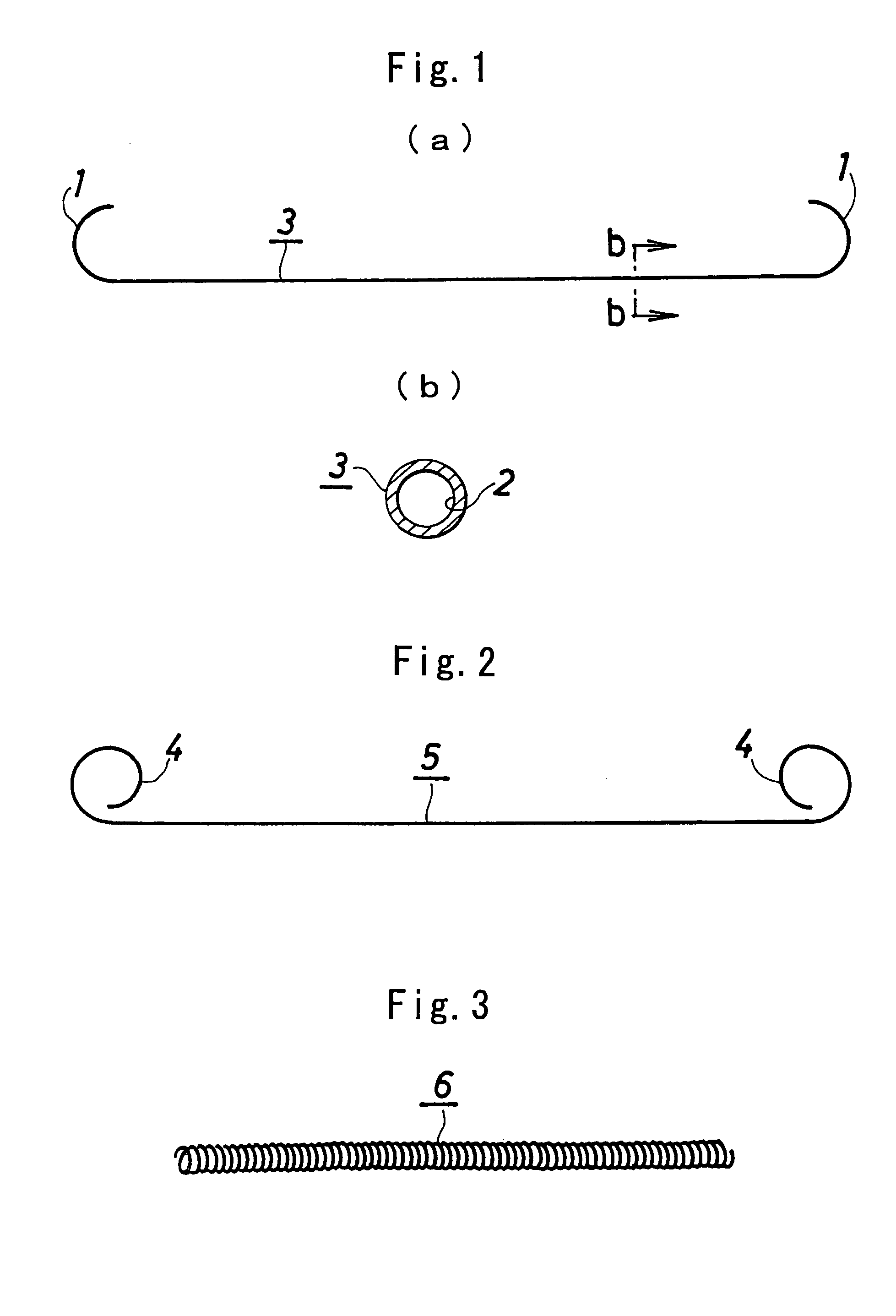
[0039] Poly(L-lactic acid) (product of Shimadzu Corp., trade name “Lacty,” 200,000 in weight average molecular weight, 175° C. in melting point) was melt-spun at 200° C. and drawn to obtain a hollow monofilament 0.15 mm in outside diameter and 0.12 mm in inside diameter. The monofilament was cut to a length of 8 cm. Each of opposite ends of the cut piece was wound around a stainless steel mandrel, 1 mm in diameter, one-half turn, held in J-shaped curl, heat-treated at 150° C. and then cooled. In this way, a bioabsorbable vasoocclusive coil 3 was prepared which had a J-shaped curved portion 1 at each of opposite ends thereof and a hollow portion 2 over the entire length thereof as shown in FIG. 1.

example 2

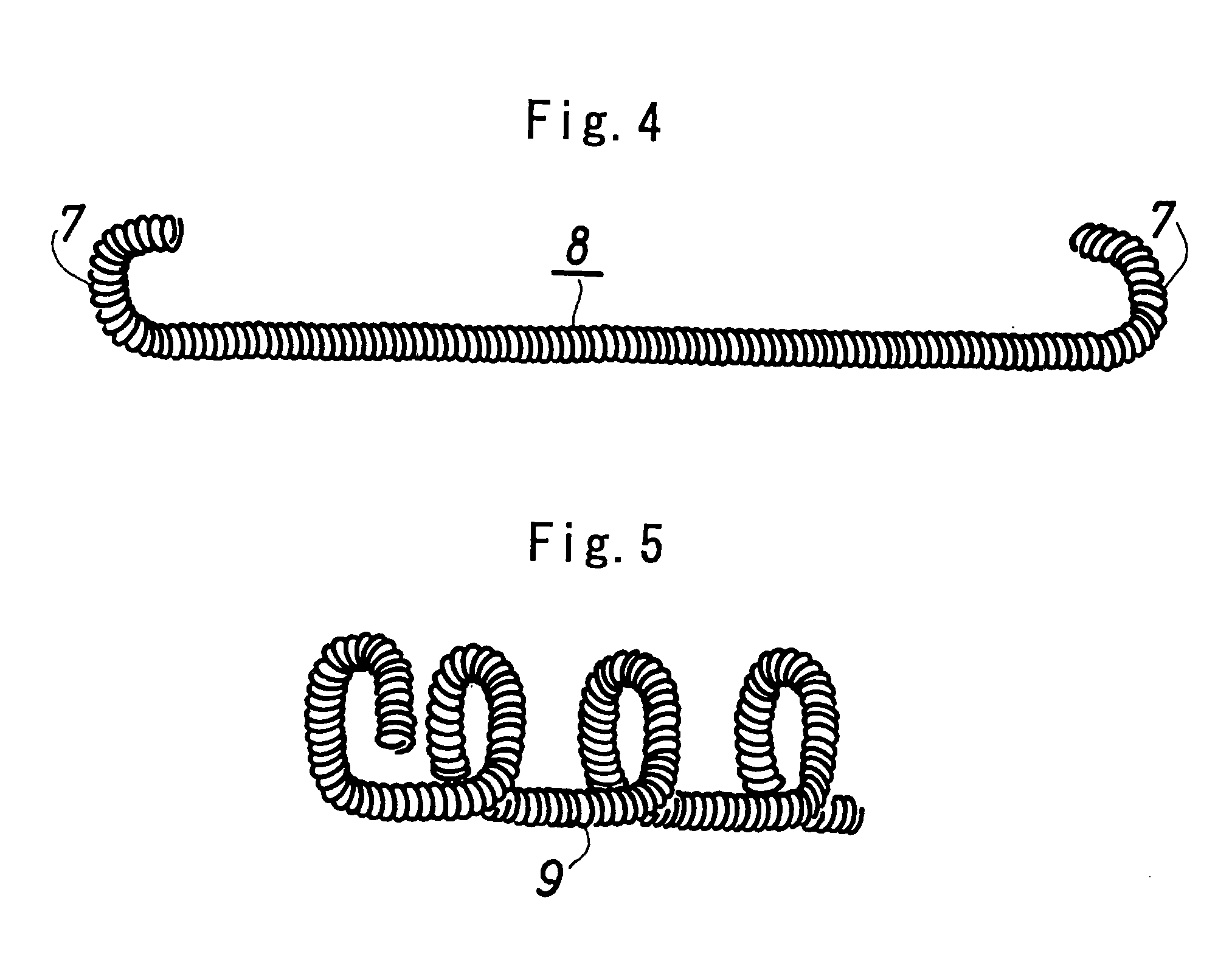
[0040] The hollow monofilament of poly (L-lactic acid) produced in Example 1 and having an outside diameter of 0.15 mm and an inside diameter of 0.12 mm was cut to a length of 60 cm. Each of opposite ends of the cut piece was wound around a stainless steel mandrel, 1 mm in diameter, one turn, held in the form of a circular loop, heat-treated at 150° C. and then cooled. In this way, a bioabsorbable hollow vasoocclusive coil 5 was prepared which had a circular loop portion 4 at each of opposite ends thereof as shown in FIG. 2.

[0041] The vasoocclusive coil was inserted as stretched substantially straight into the base end of a microcatheter measuring 1 mm in outside diameter and 110 cm in entire length and filled with physiological saline, and advanced to the catheter distal end, from which the coil was pushed out of the catheter. The coil thereafter restored itself to the shape of circular loop at each end thereof.

example 3

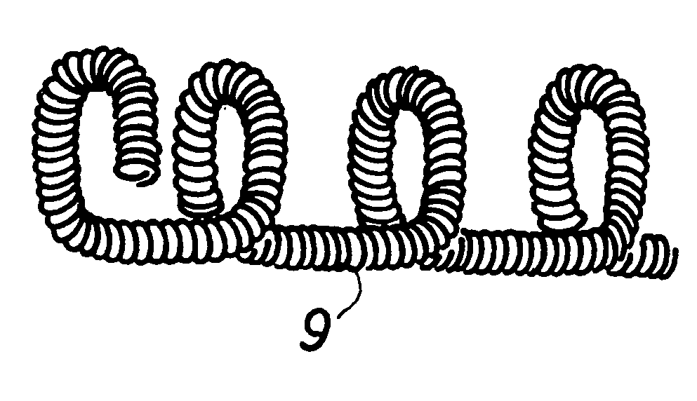
[0042] The hollow monofilament of poly(L-lactic acid) produced in Example 1 and having an outside diameter of 0.15 mm and an inside diameter of 0.12 mm was cut to a length of 60 cm. The cut piece was helically wound around a straight stainless steel mandrel, 2 mm in diameter, heat-treated at 150° C. and then cooled. The winding was thereafter removed from the mandrel. In this way, a bioabsorbable hollow vasoocclusive coil 6 was prepared which was about 5 cm in length and in the form of a helical winding as shown in FIG. 3.


PUM

PropertyMeasurementUnit
diameteraaaaaaaaaa
diameteraaaaaaaaaa
diameteraaaaaaaaaa

Abstract

Poly(L-lactic acid) was melt-spun at 200° C. and drawn to obtain a hollow monofilament 0.15 mm in outside diameter and 0.12 mm in inside diameter. The monofilament was cut to a length of 8 cm. Each of opposite ends of the cut piece was wound around a stainless steel mandrel, 1 mm in diameter, one-half turn, held in J-shaped curl, heat-treated at 150° C. and then cooled. In this way, a bioabsorbable vasoocclusive coil 3 of the invention was prepared which had a J-shaped curved portion 1 at each of opposite ends thereof and a hollow portion 2 over the entire length thereof. The hollow portion can be filled with a drug such as carcinostatic or antitumor agent, permitting the drug to exhibit a sustained release effect. When the follow portion is filled with an X-ray contrast mediums the coil can be delivered to a desired intravascular site reliably, while the process of treatment can be observed more reliably.

Description

BACKGROUND OF THE INVENTION [0001] (a) Field of the Invention [0002] The present invention relates to coils for use in blood vessels of patients for occluding the blood vessel, and more particularly to an occlusive coil made from a material absorbable by the living body. The vasoocclusive coil provides a plug in the blood vessel for use in treating internal hemorrhage or aneurysm or suppressing the flow of blood to a tumor. [0003] (b) Description of the Prior Art [0004] Vasoocclusive coils are made by winding a wire into a helical form of small diameter. Some vasoocclusive coils are made from a primary coil thus obtained by helically winding a wire, by winding the coil into a helical form of large diameter, i.e., into a secondary coil. The vasoocclusive coil is inserted substantially straight into a catheter, then forced by a pusher to the desired site within a blood vessel, pushed out of the catheter and retained at the site. The publication of JP-A No. 1997-276280 discloses such c...

Claims


Application Information

Patent Timeline
Patent Type & Authority Applications(United States)
IPC IPC(8): A61B17/12A61B19/00A61L31/00A61B17/00A61L31/06A61L31/14A61L31/16A61M29/00
CPCA61B17/12022A61B17/12109A61B17/12145A61B19/54A61B2017/00004A61B2017/00867A61L2430/36A61L31/148A61L31/16A61L2300/40A61L2400/16A61L31/06C08L67/04A61B90/39
Inventor SATAKE, MITSUOYOKOGAWA, TORUSEKI, KEIICHI
Owner MEDICOS HIRATA
Why Eureka
Try Eureka