Transfer device

a technology of transfer device and transfer device, which is applied in the direction of erasing device, paper hanging, gearing, etc., can solve the problems of increasing aggravate usability, and easy generation of mentioned problems, so as to simplify the manufacturing process, and reduce the number of components

Inactive Publication Date: 2005-07-21
KOKUYO CO LTD
View PDF5 Cites 34 Cited by
  • Summary
  • Abstract
  • Description
  • Claims
  • Application Information

AI Technical Summary

Benefits of technology

[0006] In accordance with this arrangement, the restraining means can prevent the gear from being pulled out from the side panels and since the restraining means is arranged at a portion where the gear is axially mounted on the rotational supporting axis, namely, a portion different from the rotational center of the gear, it is possible to prevent the gear from rotational blurring that tends to be generated at a portion separated from the rotational center portion. Since a clearance between the rotational supporting axis and the gear can be set extremely small depending on a setting, a problem caused by a conventional arrangement, namely rotational blurring of the gear, can be effectively solved. The rotational blurring is caused by a somewhat big clearance between the rotational supporting axis and the gear in order to make an operation of engaging the gear and the rotational supporting axis by fittingly inserting the engaging nail arranged on the rotational supporting axis into the gear easy. In addition, this arrangement makes it possible to simplify arrangement of the rotational supporting axis and the gear compared with the conventional engaged arrangement by making use of the engaging nail. This arrangement makes it possible to improve a sliding state between the rotational supporting axis and the gear because no component such as an engaging nail exists. “A pair of side panels that hold the transferring material” includes both states; one of which is a state that the transferring material is directly held by a pair of the side panels (so called a transfer device of a dispensable cartridge type), the other of which is a state that the transferring material is indirectly held by a pair of the side panels (a transfer device of a refillable cartridge type).
[0018] In addition, if the transfer device comprises a refillable cartridge that holds at least the transferring material and the spool, and a case that accommodates the refillable cartridge detachably, wherein the side panel on which the gear is axially mounted through the rotational supporting axis is a component constituting the case, the gear will not be dropped off from the case even though the case is flipped vertically and horizontally in case of exchanging the refillable cartridge, thereby to improve usability.

Problems solved by technology

However, since conventional transfer devices have an arrangement wherein the gear and the rotational supporting axis are mutually engaged by making use of the engaging nail arranged on the rotational supporting axis, rotational blurring tends to be generated at a position separated from the position where the gear is axially mounted to the rotational supporting axis, especially at an outer edge of the gear, which aggravates usability.
Especially when a clearance between the rotational supporting axis and the gear (the cylindrical portion) is set to be a little large in order to make an operation of fitting the gear (the cylindrical portion) over the rotational supporting axis smooth, the above-mentioned problem is easily generated.
However, in accordance with this arrangement, the number of components is increased and the manufacturing process is complicated, which is not preferable in view of cost.

Method used


Image

  • Transfer device
  • Transfer device
  • Transfer device

Examples


Embodiment Construction

[0029] An embodiment of the present claimed invention will be described in detail with reference to the accompanying drawings.

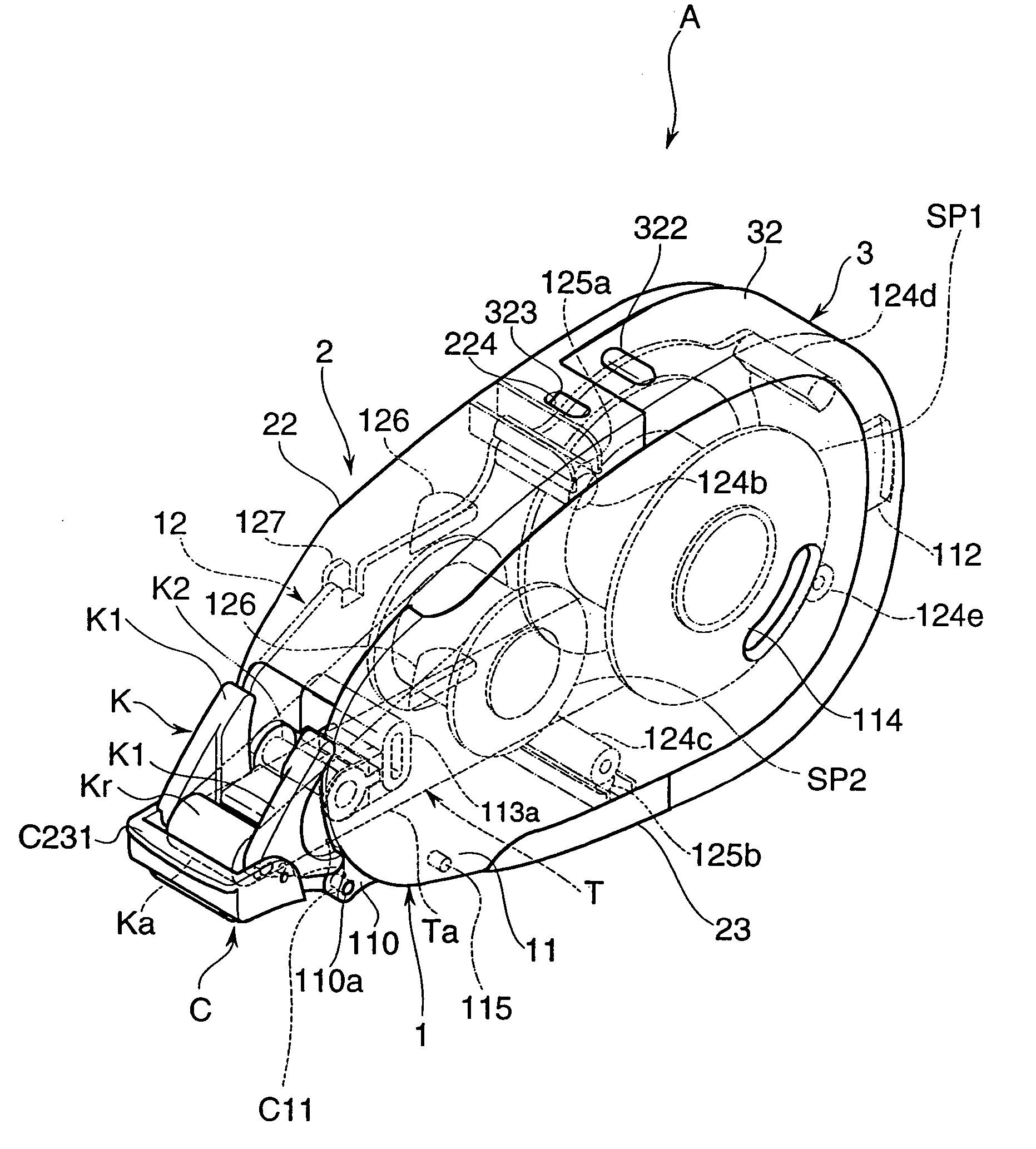
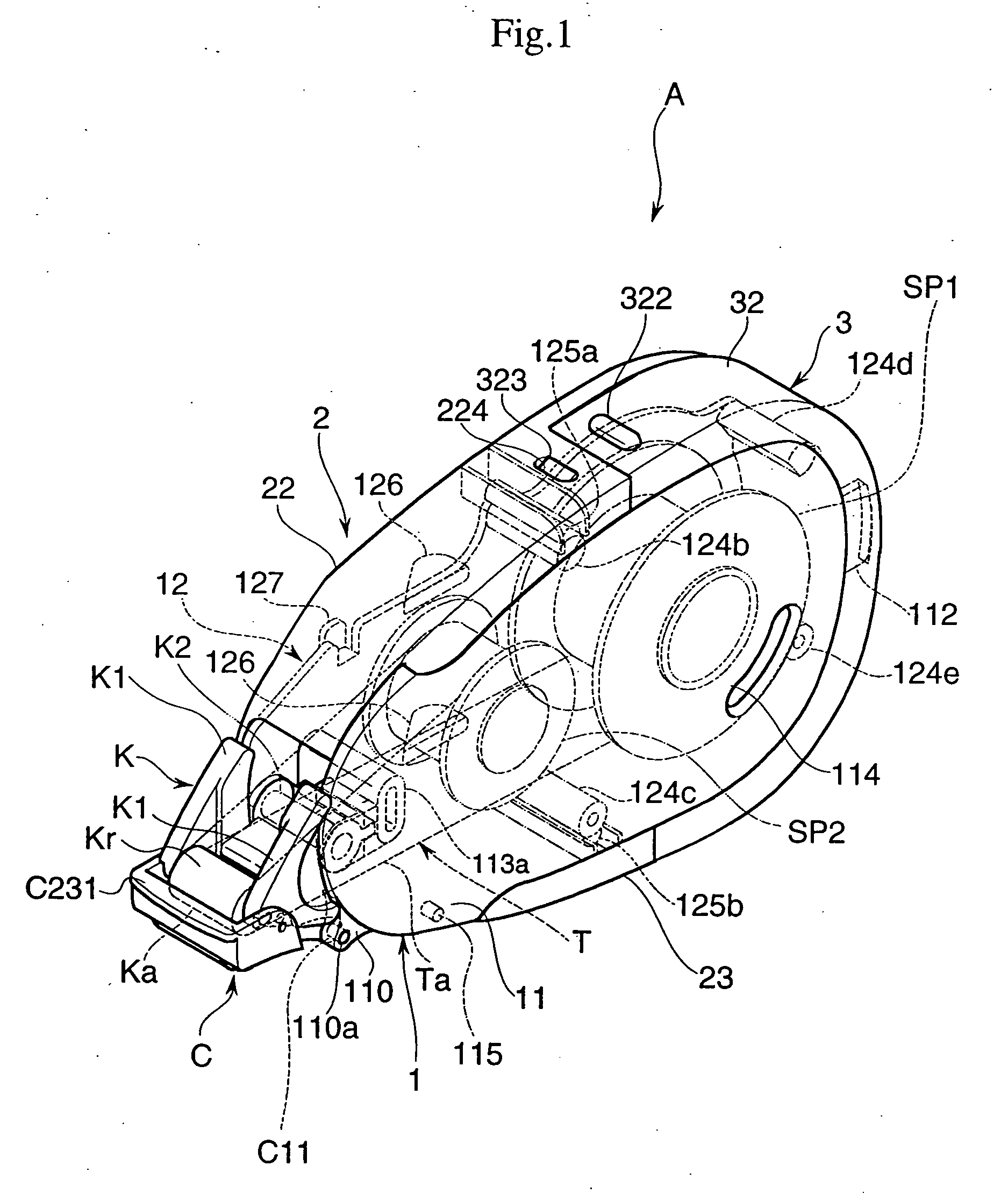
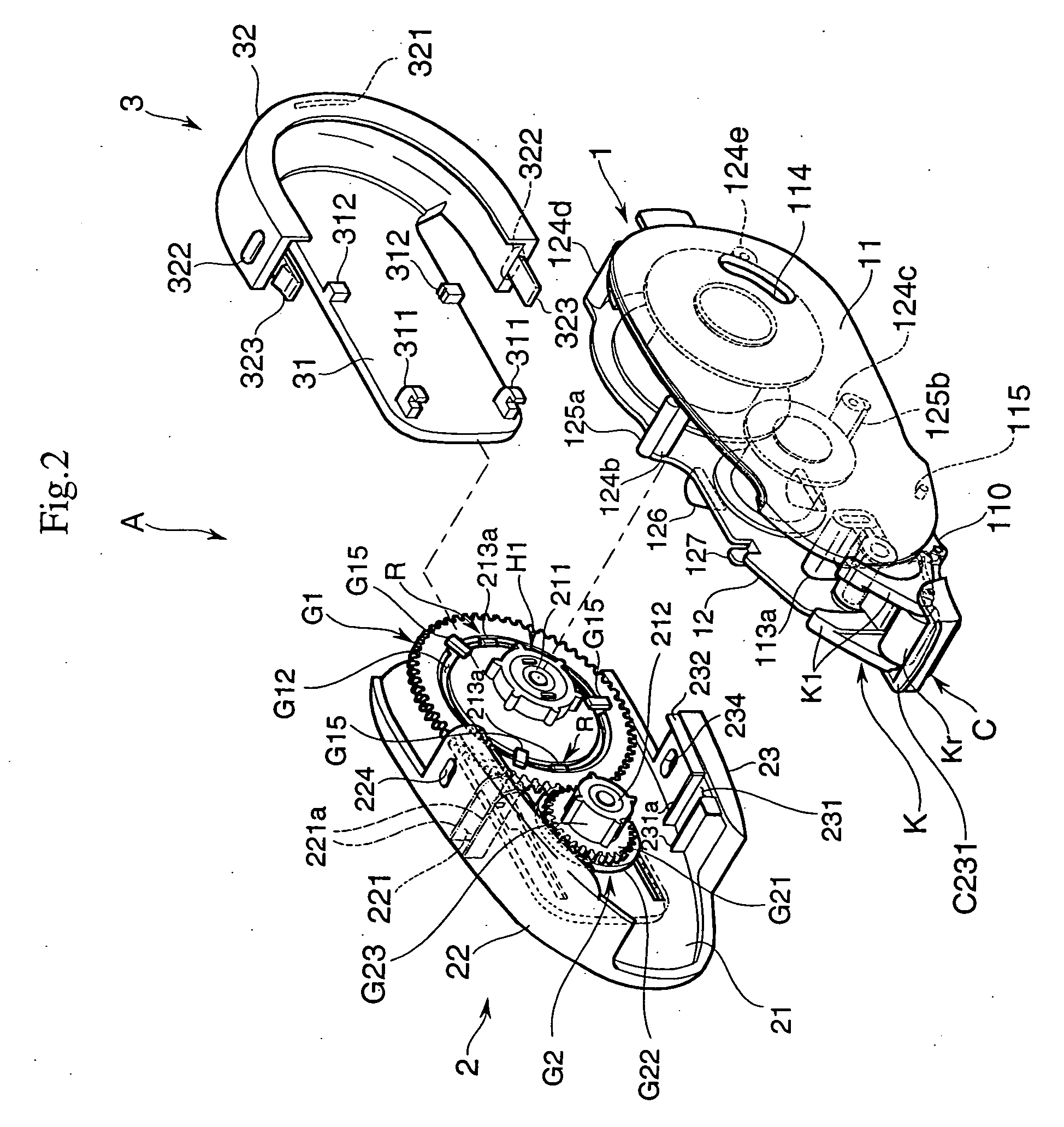
[0030] A transfer device A in accordance with this embodiment accommodates, as shown in FIG. 1 as FIG. 2, a tape body Ta and a transferring paste T as being a transferring material that is adhered to a single face of the tape body Ta in a predetermined pattern and is used for transferring the transferring paste T on an object on which the transferring paste T is to be transferred such as papers or leaves, not shown in drawings.

[0031] The transfer device A in accordance with the embodiment mainly comprises a refillable cartridge 1 that holds the transferring paste T, and a case 2 that accommodates the refillable cartridge 1 detachably, wherein a sliding member 3 that can make a sliding movement relative to the case 2 is mounted on the case 2. In the following explanation, a term “front” showing a position or a direction indicates a side where a transfer head...


PUM

PropertyMeasurementUnit
widthaaaaaaaaaa
thicknessaaaaaaaaaa
diameteraaaaaaaaaa

Abstract

A transfer device A that is used for transferring a transferring paste T on an object on which the transferring paste T is to be transferred comprises a pair of first outside panel 21 and the second outside panel 11 that hold the transferring paste T, a pair of spools SP1, SP2 that are supported rotatably by a pair of the first and second outside panels 21, 11 and that hold the transferring paste T, and a pair of gears G1, G2 that drive a pair of the spools SP1, SP2 to rotate and that gear each other, and rotational supporting axes 211, 212 that project toward the second outside panel 11 and that axially support the gears G1, G2 are arranged on the first outside panel 21, wherein a restraining means R that restrains the gear G1 from being pulled out along an axial direction of the rotational supporting axis 211 in a state that the gears G1, G2 are axially mounted on the rotational supporting axes 211, 212 is arranged between the first outside panel 21 and the gear G1 and at a portion different from a portion where the gear G1 is axially mounted on the rotational supporting axis 211.

Description

BACKGROUND OF THE INVENTION AND RELATED ART STATEMENT [0001] This invention relates to a transfer device that is used for transferring a transferring material on an object on which the transferring material is to be transferred. [0002] Various transfer devices have been conceived that are used in case of transferring a transferring material on an object on which the transferring material is to be transferred. These transfer devices are so arranged that a pair of gears are rotatably mounted on a rotational supporting axis arranged on a pair of side panels wherein the gears drive a pair of spools to rotate and gear each other in conjunction with a pair of the spools that are rotatably supported by the side panels holding the transferring material and that mount the transferring material. As an arrangement to mount these gears on the rotational supporting axis, it is represented that multiple slits are arranged along an axial direction of the supporting axis, an engaging nail is arrang...

Claims


Application Information

Patent Timeline
Patent Type & Authority Applications(United States)
IPC IPC(8): B43M11/02B43M11/06B65H37/00B43L19/00
CPCB43M11/02B43M11/06Y10T156/18Y10T156/1795Y10T156/1348B65H37/007
Inventor MITSUI, TAKASHISHIMA, HIDETO
Owner KOKUYO CO LTD
Why Eureka
Try Eureka