Dilution apparatus for a thickener

Active Publication Date: 2005-07-21
OUTOTEC OYJ
View PDF6 Cites 13 Cited by
  • Summary
  • Abstract
  • Description
  • Claims
  • Application Information

AI Technical Summary

Benefits of technology

[0013] In the preferred embodiment, the feedwell is disposed substantially within the thickening tank, the pump is positioned substantially within the tank, and all plumbing and pipe work for the pump is predominantly contained within an outer perimeter of the tank. Preferably also, the pump is positioned closely adjacent the feedwell so as to minimise intermediate plumbing and pipe work within the tank.
[0023] In the preferred embodiment, the feedwell is disposed substantially within the thickening tank, the pump is positioned substantially within the tank, and all plumbing and pipe work for the pump is substantially contained within the outer perimeter of the tank. Preferably also, the pump is positioned closely adjacent the feedwell so as to minimise intermediate plumbing and pipe work within the tank. The feedwell is preferably positioned substantially centrally within the tank.
[0029] Preferably, the method also includes the step of maintaining a relatively small head difference between a liquid surface in the feedwell and a liquid surface in the thickening tank.
[0030] In the preferred embodiment, the method includes the steps of positioning the feedwell substantially within the thickening tank, positioning the pump substantially within the tank, and containing the plumbing and pipe work for the pump substantially within the outer perimeter of the tank. Preferably also, the pump is positioning closely adjacent the feedwell so as to minimise the intermediate plumbing and pipe work within the tank.

Problems solved by technology

All of these existing methods have disadvantages.
Those utilising pumps require considerable pipework and electrical power to transfer the diluting liquid.
Conversely, the internal systems, which use differential density or momentum transfer mechanisms, are relatively simpler and require little to no electrical power, but lack means to precisely control dilution under all operating conditions.

Method used


Image

  • Dilution apparatus for a thickener
  • Dilution apparatus for a thickener
  • Dilution apparatus for a thickener

Examples


Embodiment Construction

[0034] A preferred application of the invention is in the field of mineral processing, separation and extraction, whereby finely ground ore is suspended as pulp in a suitable liquid medium, such as water, at a consistency which permits flow, and settlement in quiescent conditions.

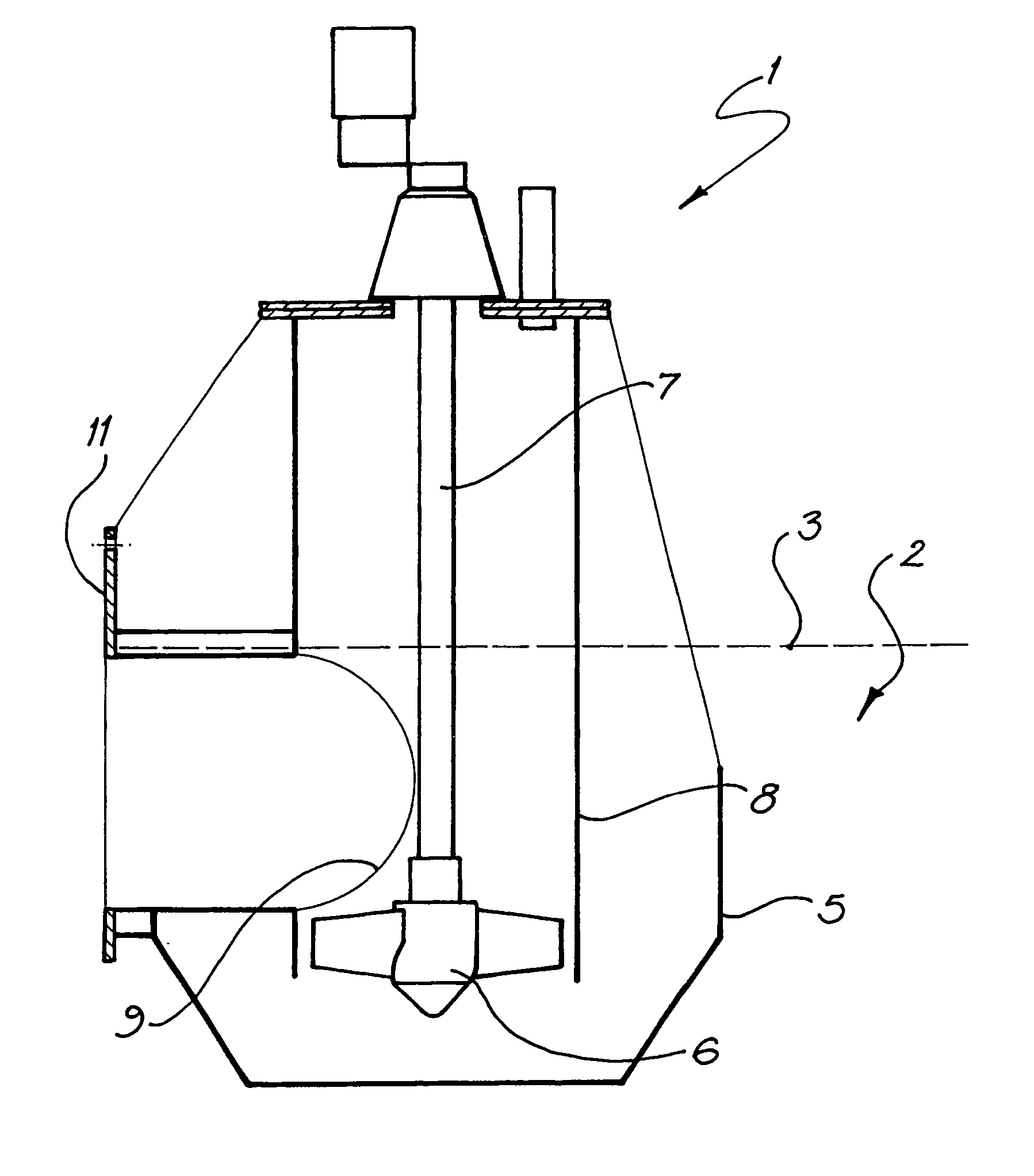
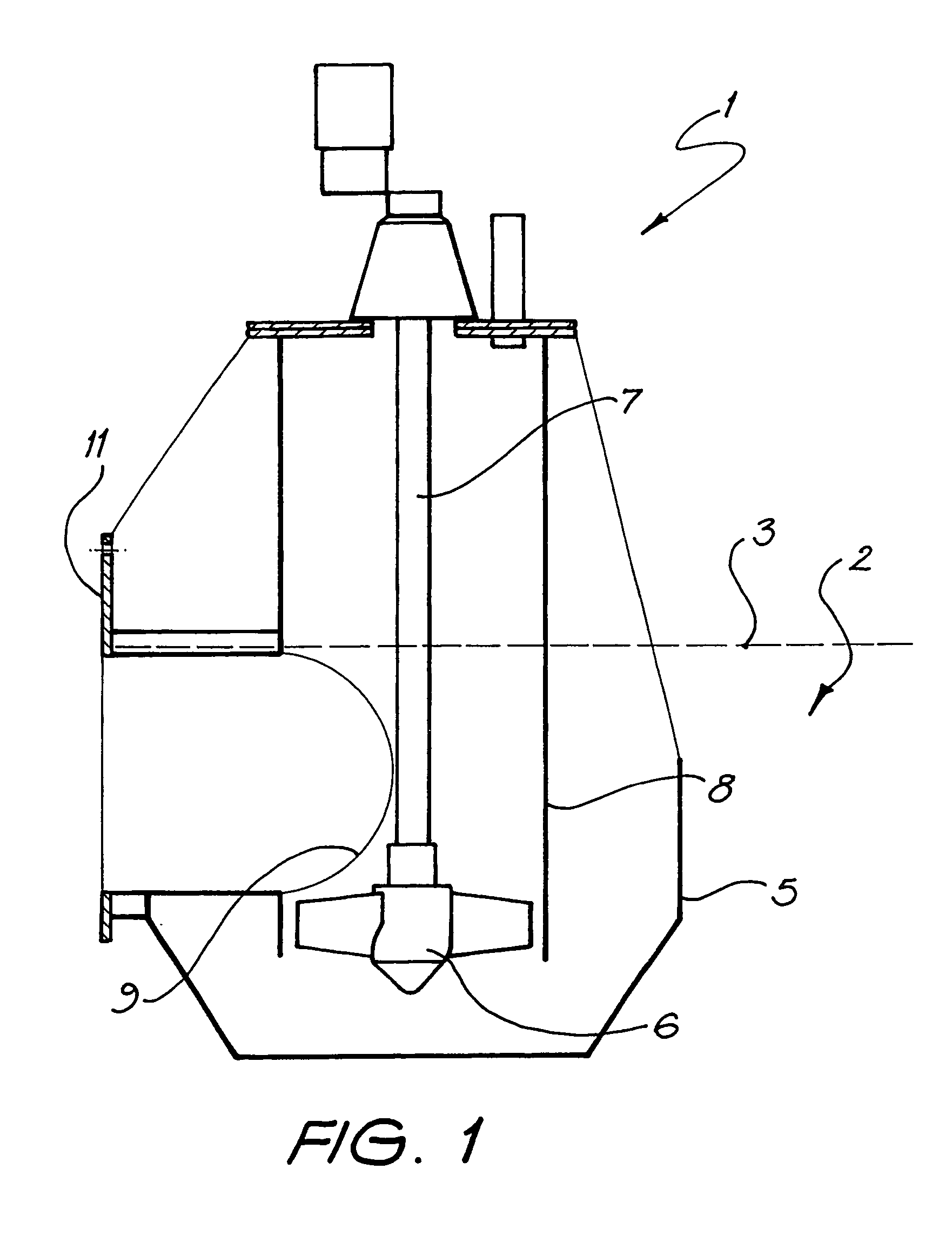
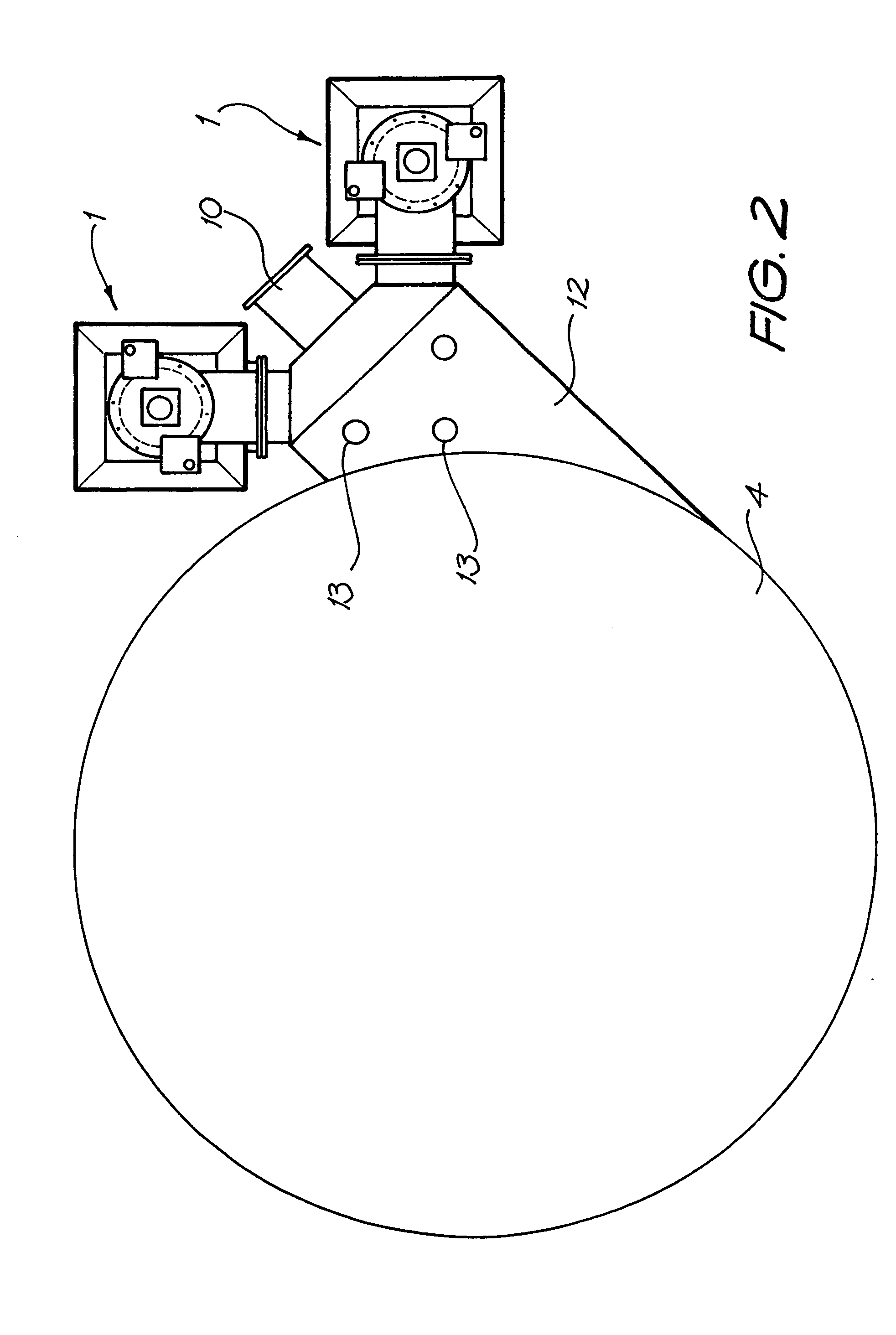
[0035] Referring to the drawings, the apparatus includes an axial flow pump 1 for accurately injecting supernatant liquid 2 from adjacent the liquid surface 3 of a thickening tank (not shown) to dilute liquid in a feedwell 4.

[0036] The pump 1 includes a cup shaped receiving vessel 5 submerged in the supernatant liquid. The pump also includes a submerged impeller 6 mounted on a rotatable shaft 7 for drawing liquid from the vessel 5 and injecting it into the feedwell 4. The shaft 7 is driven by a motor and associated gearbox (not shown). The pump is responsive to system parameters for adjusting the flow rate of the supernatant liquid. In the illustrated embodiment, the flow rate is adjusted by varying the p...


PUM

PropertyMeasurementUnit
Flow rateaaaaaaaaaa
Shapeaaaaaaaaaa
Perimeteraaaaaaaaaa

Abstract

The invention provides an axial flow pump (1) for accurately injecting supernatant liquid (2) from adjacent the liquid surface (3) of a thickening tank (not shown) to dilute liquid in a feedwell (4). The pump (1) includes a cup shaped receiving vessel (5) submerged in the supernatant liquid. The pump also includes a submerged impeller (6) mounted on a rotatable shaft (7) for drawing liquid from the vessel (5) and injecting it into the feedwell (4). The shaft (7) is driven by a motor and associated gearbox (not shown). The pump is responsive to system parameters for adjusting the flow rate of the supernatant liquid.

Description

FIELD OF THE INVENTION [0001] The present invention relates to separation devices for liquid suspensions and pulps and in particular to recycling of overflow liquor in thickeners. It has been developed primarily for use in separating mineral pulp from a liquid suspension and will be described hereinafter with reference to this application. However, it will be appreciated that the invention is not limited to this particular field of use. BACKGROUND OF THE INVENTION [0002] The following discussion of the prior art is intended to present the invention in an appropriate technical context and allow its significance to be properly appreciated. Unless clearly indicated to the contrary, however, reference to any prior art in this specification should not be construed as an admission that such art is widely known or forms part of common general knowledge in the field. [0003] Thickeners are known as a means of separating suspended pulps. They are commonly used in the field of mineral processi...

Claims


Application Information

Patent Timeline
IPC IPC(8): B01D21/24B01D21/30B01D21/34C02F1/52D21H13/36
CPCB01D21/0018B01D21/2488B01D21/2405
Inventor TAYLOR, DAVID JOHN BUCHANANBELKE, JEFFREY VICTOR
Owner OUTOTEC OYJ
Why Eureka
Try Eureka