
Method of testing a battery pack by purposeful charge/discharge operations

Inactive Publication Date: 2005-07-21
HANDSUN ELECTRONICS ENTERPRISE +2
View PDF5 Cites 31 Cited by
  • Summary
  • Abstract
  • Description
  • Claims
  • Application Information

AI Technical Summary

Benefits of technology

[0011] The main objective of the present invention is to provide a method that enables a battery pack to discharge / charge purposely even when an external power is normal and available, so as to facilitate the recording of the characteristic data for accurate estimation of the battery pack capacity and the remaining service life.

Problems solved by technology

However, the battery pack is rarely used or put through a discharge test in the normal condition.
For a lead acid battery pack, it is possible to measure the specific gravity of the solution in the battery pack to estimate the battery capacity, but for hermetically sealed batteries, it will be difficult to determine the battery capacity merely by observing the appearance of the battery pack.
Therefore, maintenance personnel without any test data cannot tell whether the battery capacity of a standby battery pack has significantly changed or deteriorated, as the battery capacity will decrease when internal battery cells deteriorate or the operating temperature goes up too high.
However, since the foregoing battery test method has to be conducted in a power off condition, considerable risk is involved.
Even when the line power is interrupted, the system is still capable of recording the characteristic data from a discharging battery pack, but the accuracy in the estimation of capacity may be affected due to the relatively short recording interval assigned for each battery pack.
However, the circuit still does not disclose a testing method for the batteries to ensure these batteries can normally supply power to the load while the power of the charger 20 is interrupted.

Method used


Image

  • Method of testing a battery pack by purposeful charge/discharge operations
  • Method of testing a battery pack by purposeful charge/discharge operations
  • Method of testing a battery pack by purposeful charge/discharge operations

Examples


Embodiment Construction

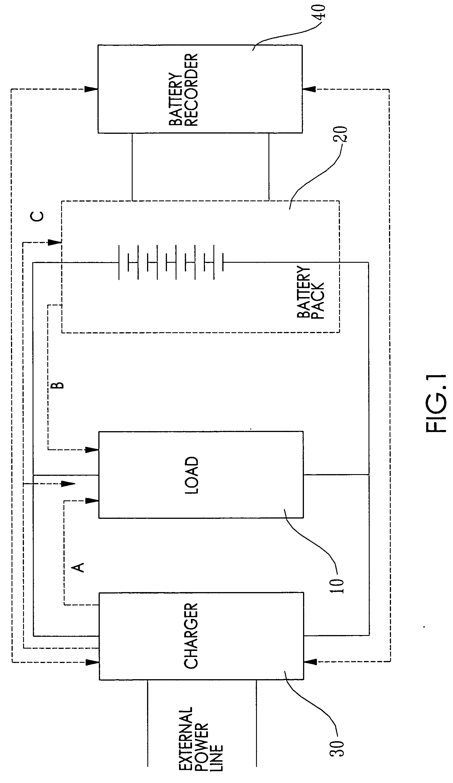
[0021] With reference to FIG. 1, a system architecture in accordance with the present invention shows a load (10) connected to a battery pack (20), and also connected to an external power line through a charger (30) in parallel. Under the normal power condition, the load (10) obtains the operating power from the external power line through the charger (30) as indicated by path A, and the battery pack (20) connected to the charger (30) is placed in a floating charge mode (standby mode) and remains at a floating charge potential.

[0022] The battery pack (20) can be coupled with a recorder (40) for recording the battery discharging data. The charger (30) in accordance with the preferred embodiment can be implemented by an uninterrupted power supply (UPS). It is noted that the charger (30) can based on the status of the battery pack (20) to charge the battery pack (20), and the output voltage potential of the charger (30) is able to be purposely controlled at a desired level.

[0023] Bas...


PUM


Abstract

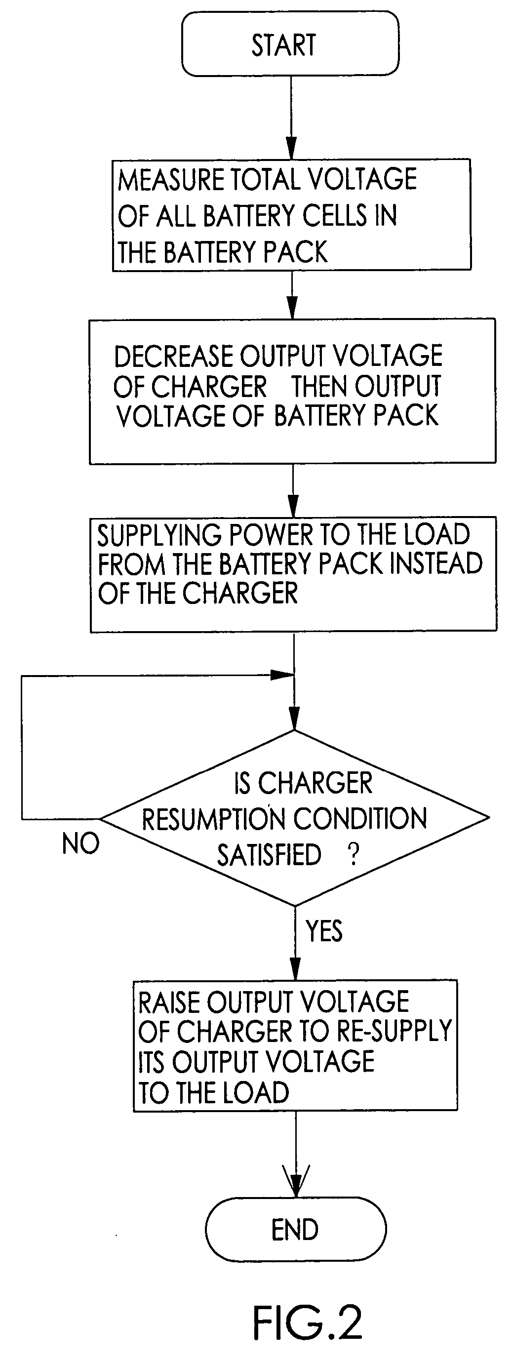
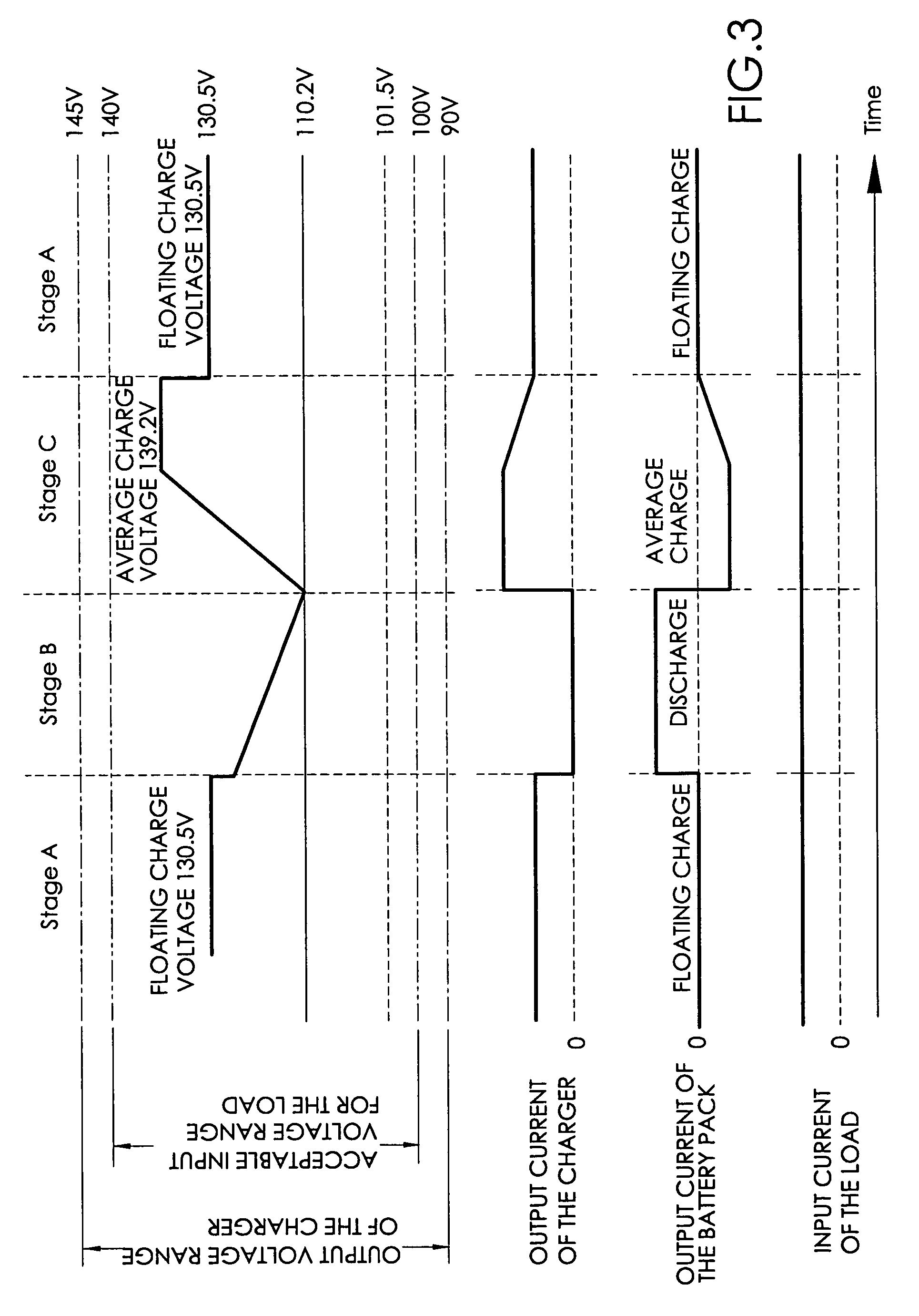
A method of testing a battery pack, wherein a load is connected to a charger and the battery pack, and receives power supply from either the external charger or the battery pack. When the external power line is normally supplied to the load through the charger, the battery pack is purposely enabled to start its discharge and to supply power to the load. When the output voltage of the battery pack drops below a threshold level or the discharging time exceeds a preset limit, the charger re-supplies its output voltage to the load and to charge the battery pack. By the purposeful charge / discharge operations, characteristic data of the battery pack are collected and recorded for estimation of the battery pack capacity and the remaining service life.

Description

CROSS REFERENCE TO RELATED APPLICATION [0001] The application is a continuation in part of U.S. patent application Ser. No. 10 / 404,555 filed Apr. 2, 2003.BACKGROUND OF THE INVENTION [0002] 1. Field of the Invention [0003] The present invention relates to a method of testing a secondary battery pack, in particular to a method which enforces the secondary battery pack to have charge / discharge operations even when an external power is available, so that characteristic data of the secondary battery can be collected and recorded for estimation of the battery pack capacity and the remaining service life. [0004] 2. Description of Related Arts [0005] Uninterrupted power supply (UPS) is widely employed in computers, communication systems and laboratories for protecting instruments and equipment from sudden power failures. The main component in a UPS is the battery pack. When the line power (external power) is normal, the battery pack is placed on a standby situation, but when the line power ...

Claims


Application Information

Patent Timeline
IPC IPC(8): G01R31/36H02J7/00
CPCG01R31/3631H02J7/0068H02J7/0047G01R31/386H02J7/0048H02J7/005
Inventor LIN, HSIN-ANTSAI, KUO-HSIEN
Owner HANDSUN ELECTRONICS ENTERPRISE
Learn More