
Tire condition display device

Inactive Publication Date: 2005-07-21
TOYOTA JIDOSHA KK
View PDF2 Cites 8 Cited by
  • Summary
  • Abstract
  • Description
  • Claims
  • Application Information

AI Technical Summary

Benefits of technology

[0010] Accordingly, the present invention is made in view of the above-mentioned problems, and aims at offering a tire condition display device in which tire condition information detected by sensors mounted at wheels in a vehicle is displayed together with the corresponding tire mounting locations, and such corresponding relations can be easily input.
[0017] In case a where each of the sensors is previously assigned a unique identification number, the identification signs and the identification numbers can be related to each other. In this case, the car receives the sensor identification number, and the identification signs are also available. Therefore, it is not required anymore to transmit the identification signs from the wheels to the car, and the amount of data communicated is reduced.
[0018] In a tire condition display device according to the present invention, tire condition information detected by a sensor mounted at a wheel can be displayed together with the location of the wheel, and corresponding relations between the identification signs and the locations of the wheel can be easily obtained.

Problems solved by technology

If such input is wrong, tire conditions cannot be detected correctly, and further there is no way of confirming the correct wheel locations.
Therefore it is impossible to identify the abnormal wheel-location without getting out of the car.

Method used


Image

  • Tire condition display device
  • Tire condition display device
  • Tire condition display device

Examples


Embodiment Construction

[0025] In the following, embodiments of the present invention are described with reference to the accompanying drawings.

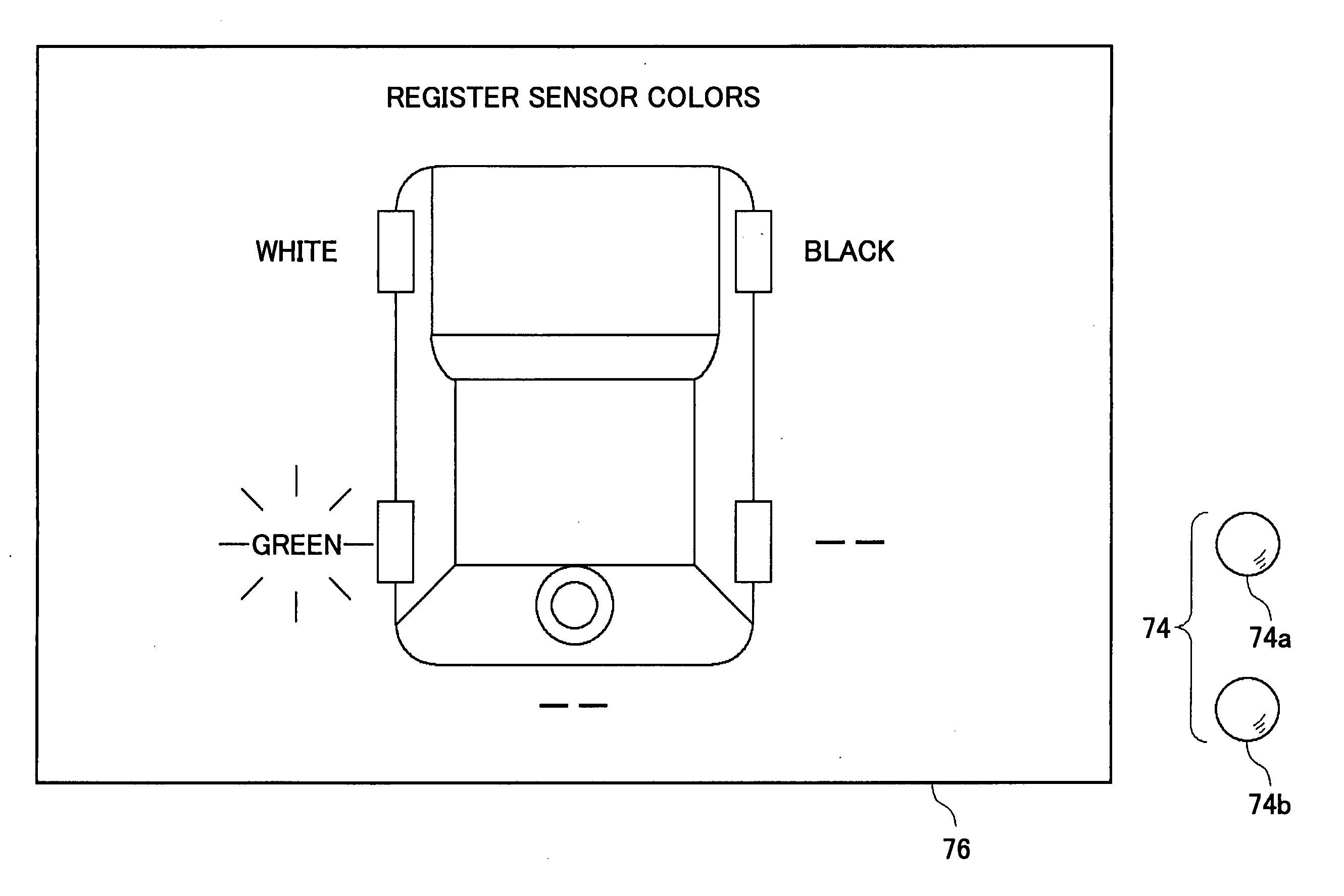
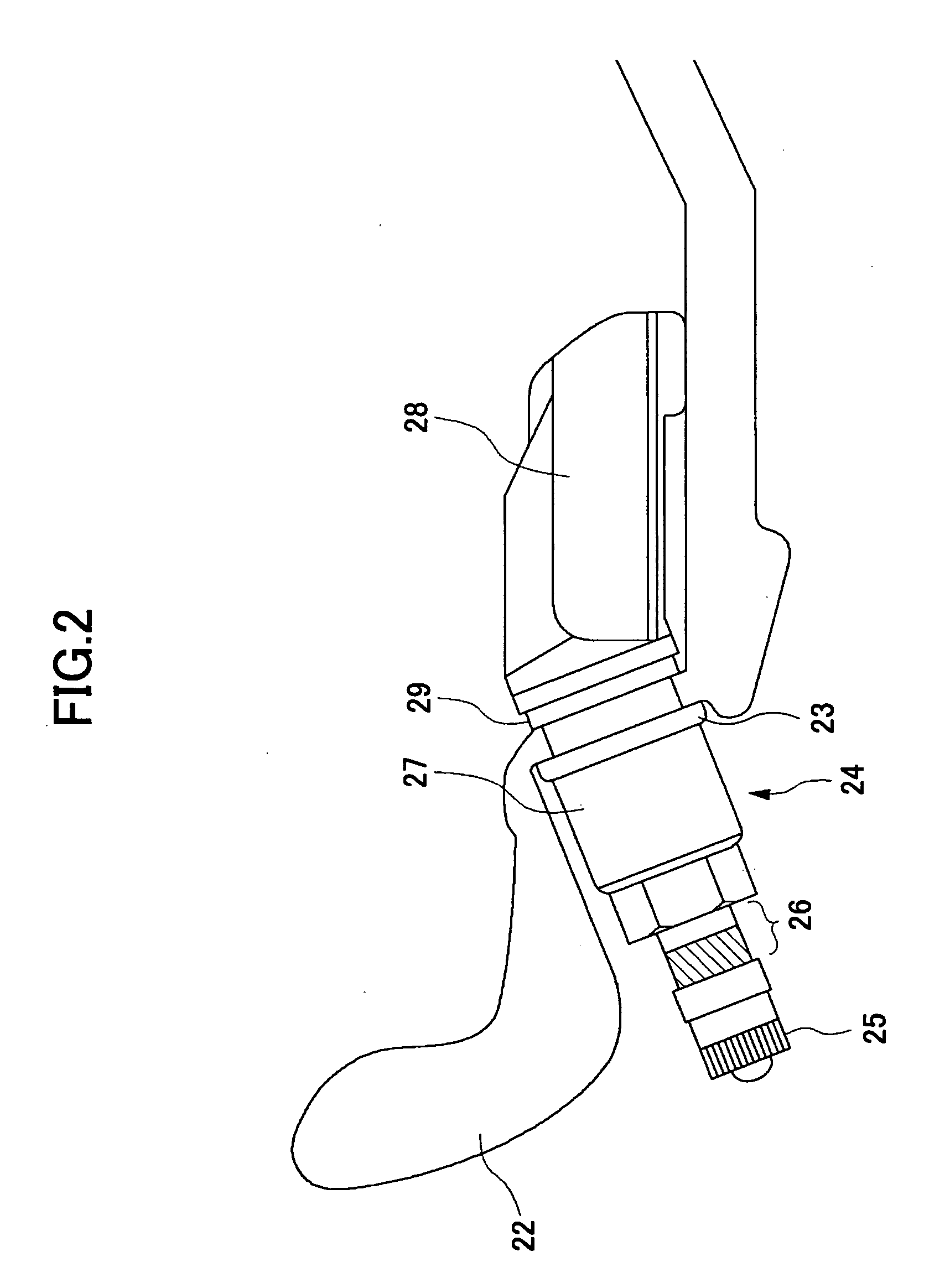
[0026] According to one embodiment of the present invention, in a tire condition display system incapable of identifying tires provided with sensors based only on information transmitted from the tires, an identification sign is attached to an air valve of each tire. After replacing tires, a user inputs the corresponding relation between the identification sign and its tire's location (FR, FL, RR and RL) in a car, so that air pressure of each tire can be displayed with its tire's location in the car.

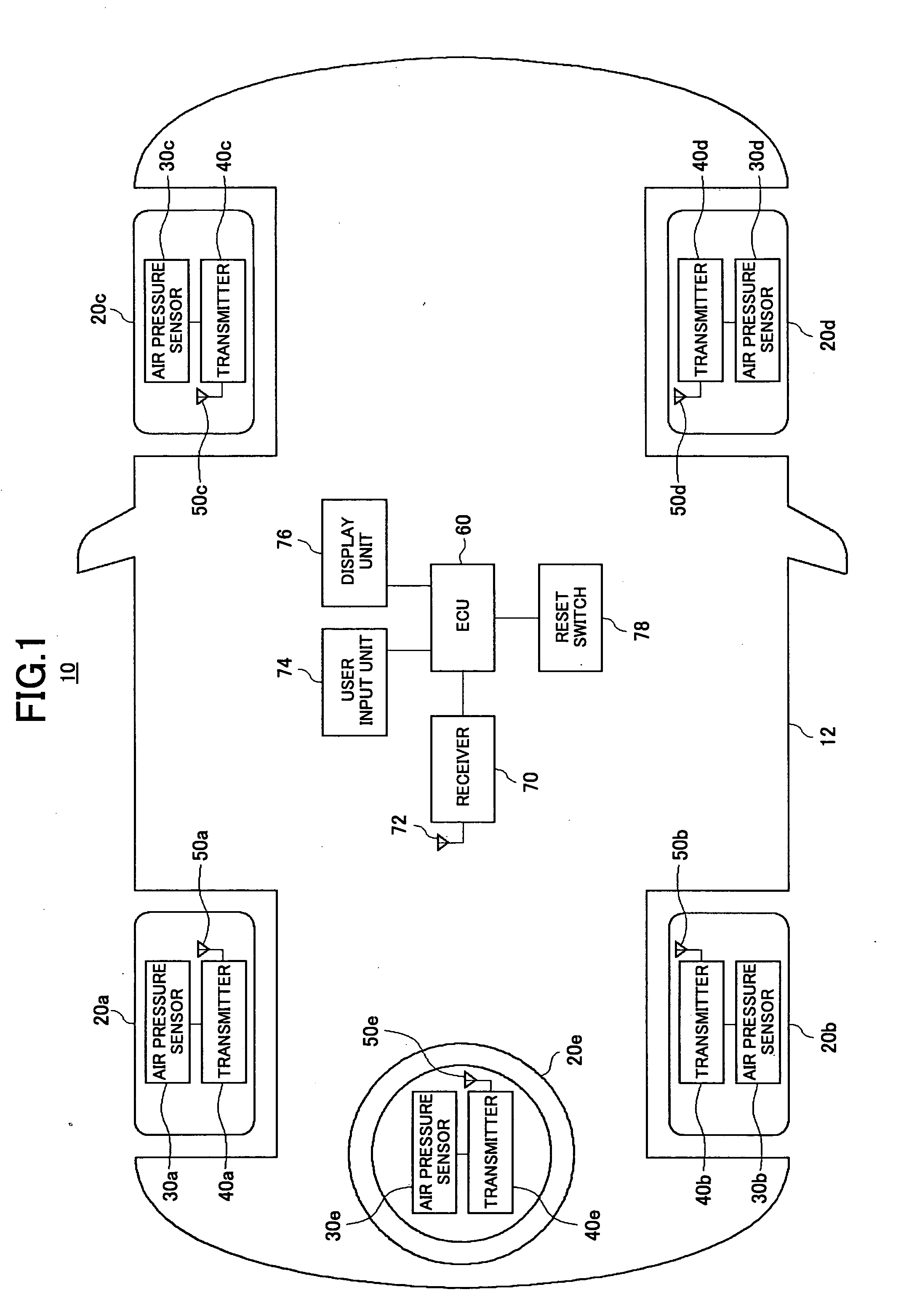
[0027]FIG. 1 generally shows a car 12 comprising a tire condition display system 10 according to one embodiment of the present invention. To each of four wheels and a spare tire of the car 12, an air pressure sensor for detecting the air pressure of its tire, a transmitter for transmitting the tire air pressure detected by the air pressure sensor to the car, and an an...


PUM


Abstract

A tire condition display device is disclosed. The device comprises plural sensors for detecting tire condition, each of the sensors being mounted at a wheel of a vehicle and having a different identification sign at an observable place; a transmitter mounted at each wheel, for transmitting the tire condition information detected by the sensor and the identification sign; a user input unit for receiving corresponding relations between the identification signs and corresponding wheel locations in the vehicle; and a display unit for displaying the tire condition information and corresponding wheel locations, based on the received corresponding relations.

Description

BACKGROUND OF THE INVENTION [0001] 1. Field of the Invention [0002] The present invention relates to a tire condition display device capable of showing tire condition information such as tire air pressure detected by a sensor mounted at each wheel, together with the corresponding tire locations in a vehicle. [0003] 2. Description of the Related Art [0004] In order to drive a car safely, it is necessary to keep wheel conditions including tire conditions normal. Therefore, when an abnormal condition such as low tire air pressure occurs in a wheel, the abnormal condition should be immediately detected and treated properly. [0005] As a prior technology for alerting a user to abnormal conditions occurring in tires, Patent Reference 1 discloses a tire pressure monitoring system comprising a tire pressure alarming lamp corresponding to the wheel location. Patent Reference 2 discloses a technology in which plural tires are provided with sensors having different identification signs. When a ...

Claims


Application Information

Patent Timeline
IPC IPC(8): B60C23/00G01D7/00B60C23/02B60C23/04B60K35/00G01L17/00G08C17/02
CPCB60C23/0408B60C23/0401
Inventor OGAWA, ATSUSHI
Owner TOYOTA JIDOSHA KK
Learn More