
Music analysis apparatus

Active Publication Date: 2011-11-10
YAMAHA CORP
View PDF4 Cites 8 Cited by
  • Summary
  • Abstract
  • Description
  • Claims
  • Application Information

AI Technical Summary

Benefits of technology

[0006]The invention has been made in view of these circumstances and it is an object of the invention to reduce processing load required to compare rhythms of pieces of music while reducing the amount of data required to analyze rhythms of pieces of music.
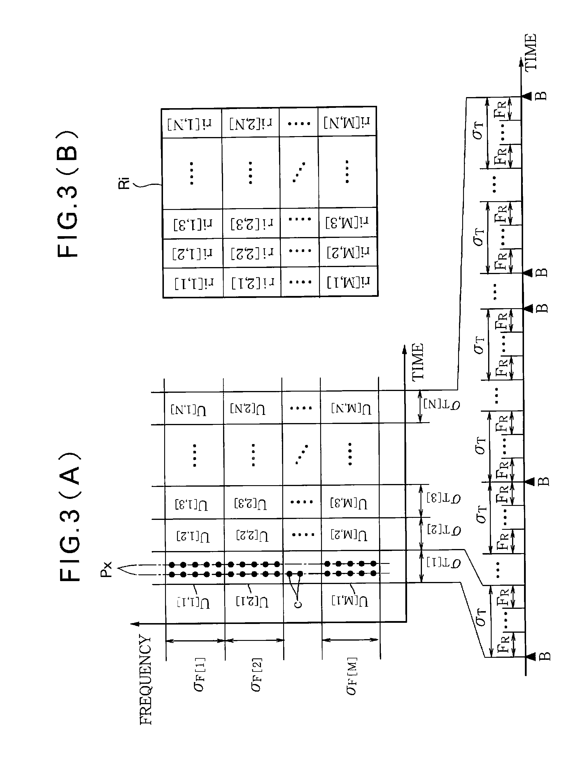
[0008]In this configuration, the feature values of the rhythmic feature amount are calculated using analysis periods, each including a plurality of unit periods, as time-axis units and therefore there is an advantage in that the data volume of the rhythmic feature amount is reduced compared to the prior art configuration in which a feature value is calculated for each unit period. In addition, it is possible to compare audio signals with each other with reference to the common time axis even when the audio signals have different tempos, since the analysis periods are defined with reference to beats of the piece of music. Accordingly, compared to the prior art configuration of the technology disclosed by Jouni Paulus and Anssi Klapuri, “Measuring the Similarity of Rhythmic Patterns”, Proc. ISMIR 2002, p. 150-156 in which there is a need to match the time axis of each audio signal to be compared, there is an advantage in that processing load required to compare the rhythms of pieces of music is reduced. The term “piece of music” or “music” used in the specification refers to a set of musical sounds or vocal sound arranged in a time series, no matter whether it is all or part of a piece of music created as a single work. Although the frequency bandwidth of each analysis band is arbitrary, it is preferable to employ a configuration in which each analysis band is set to a bandwidth corresponding to, for example, one octave.
[0018]In this aspect, the feature values of the rhythmic feature amount are calculated respectively for analysis periods, each including a plurality of unit periods, as time-axis units and therefore there is an advantage in that the amount of data required for the storage part is reduced compared to the prior art configuration in which a feature value is calculated for each unit period. In addition, it is possible to contrast audio signals with each other with reference to the common time axis even when the audio signals have different tempos since analysis periods are normalized with reference to beats of the piece of music. Accordingly, there is an advantage in that processing load required to compare the rhythms of pieces of music is reduced.

Problems solved by technology

150-156 has a problem in that the amount of data required to compare pieces of music is large since a feature amount extracted in each unit period of audio signals is used to compare rhythms of pieces of music.
In addition, since a feature amount extracted in each unit period is set regardless of the tempo of music, an audio signal extension / contraction process such as the above-mentioned DP matching should be performed to compare the rhythms of pieces of music, causing high processing load.

Method used


Image

  • Music analysis apparatus
  • Music analysis apparatus
  • Music analysis apparatus

Examples


first embodiment

A: First Embodiment

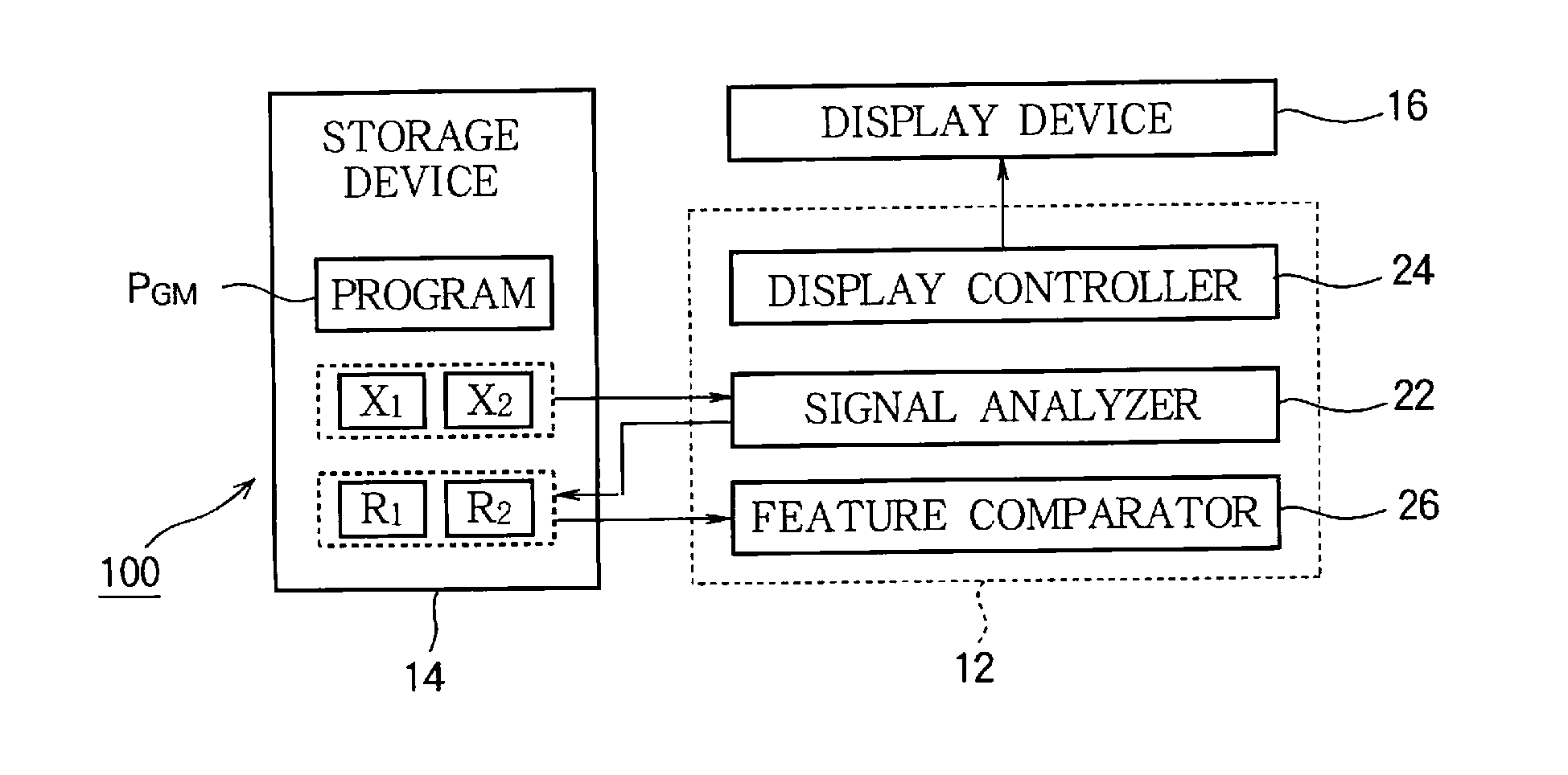
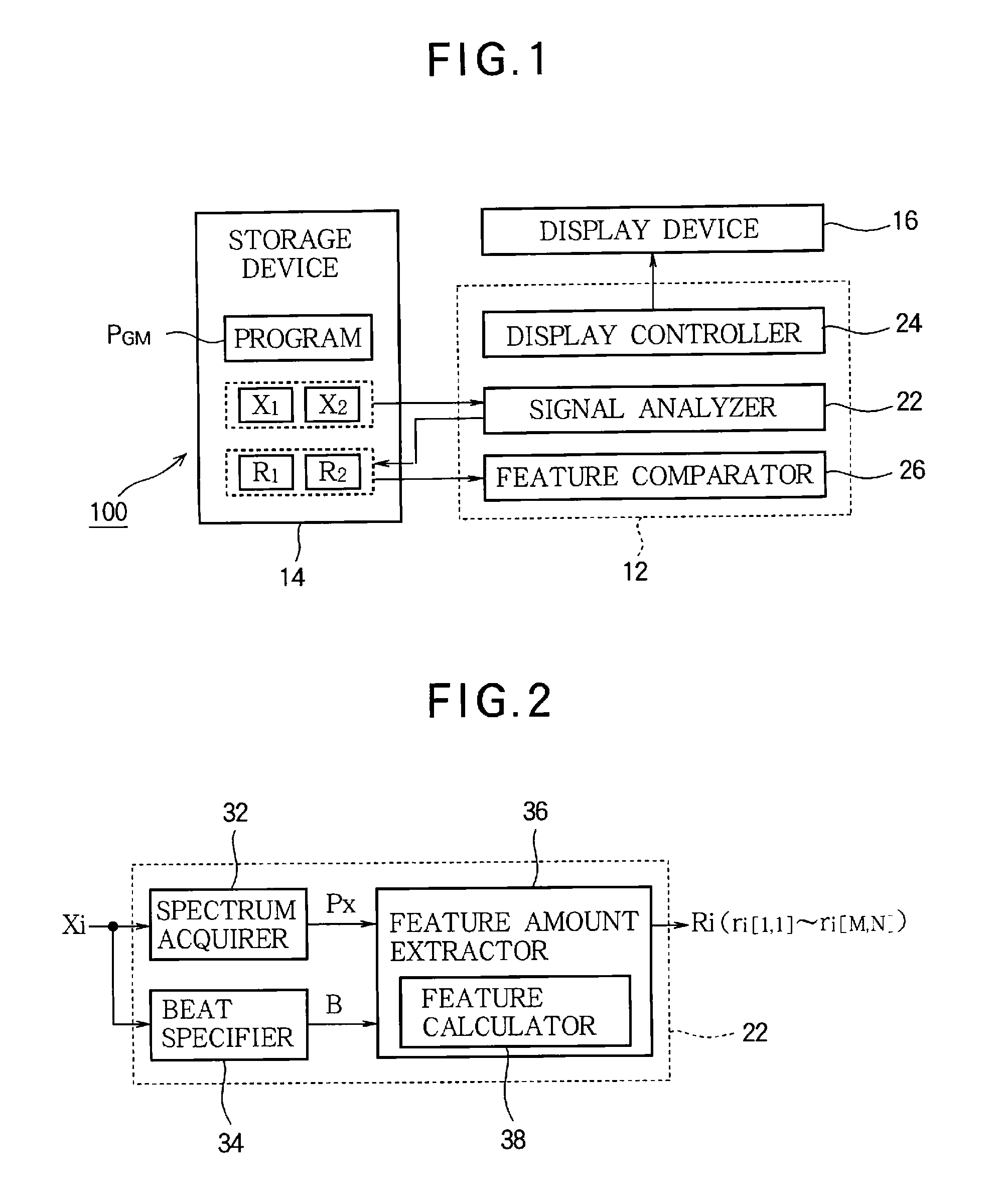
[0030]FIG. 1 is a block diagram of a musical analysis apparatus 100 according to a first embodiment of the invention. The musical analysis apparatus 100 is a device for analyzing the rhythm of music (i.e., the structure of a temporal array of musical sounds) and is implemented through a computer system including an arithmetic processing unit 12, a storage device 14, and a display device 16.

[0031]The storage device 14 stores various data used by the arithmetic processing unit 12 and a program PGM executed by the arithmetic processing unit 12. Any known machine readable storage medium such as a semiconductor recording medium or a magnetic recording medium or a combination of various types of recording media may be employed as the storage device 14.

[0032]As shown in FIG. 1, the storage device 14 stores an audio signal X1 and an audio signal X2. The audio signal Xi (i=1, 2) is a signal representing temporal waveforms of musical sounds such as singing sounds or musical...

second embodiment

B: Second Embodiment

[0059]Reference will now be made to the second embodiment of the invention. In the first embodiment, the rhythmic feature amount Ri generated by the signal analyzer 22 is corrected using the correction value sequence ATi and the other correction value sequence AFi upon comparison by the feature comparator 26. In the second embodiment, the rhythmic feature amount Ri obtained through correction by the feature comparator 26 is generated by the signal analyzer 22. In each of the following examples, elements whose operations and functions are similar to those of the first embodiment will be denoted by the reference numerals or symbols used in the above description and a detailed description thereof will be omitted as appropriate.

[0060]FIG. 7 is a block diagram of the feature amount extractor 36A in the second embodiment. FIG. 8 illustrates operation of the feature amount extractor 36A. As shown in FIG. 7, the feature amount extractor 36A of the second embodiment inclu...


PUM


Abstract

In a musical analysis apparatus, a spectrum acquirer acquires a spectrum for each frame of an audio signal representing a piece of music. A beat specifier specifies a sequence of beats of the audio signal. A feature amount extractor divides an interval between the beats into a plurality of analysis periods such that one analysis period contains a plurality of frames, and separates the spectrum of the frames contained in one analysis period into a plurality of analysis bands so as to set a plurality of analysis units in one analysis period in correspondence with the plurality of the analysis bands, such that one analysis unit contains components of the spectrum belonging to the corresponding analysis band. The feature amount extractor further calculates a feature value of each analysis unit based on the components of the spectrum contained in each analysis unit, thereby generating a rhythmic feature amount that is an array of the feature values calculated for the analysis units and that features a rhythm of the piece of music.

Description

BACKGROUND OF THE INVENTION[0001]1. Technical Field of the Invention[0002]The present invention relates to a technology for analyzing rhythms of pieces of music.[0003]2. Description of the Related Art[0004]A technology for analyzing the rhythm of music (i.e., the structure of a temporal array of musical sounds) in order to realize music comparison or search has been suggested in the art. For example, Jouni Paulus and Anssi Klapuri, “Measuring the Similarity of Rhythmic Patterns”, Proc. ISMIR 2002, p. 150-156 describes a technology in which the time sequence of the feature amount of each of unit periods (frames) having a predetermined time length, into which an audio signal is divided, is compared between different pieces of music. A DP matching (Dynamic Time Warping (DTW)) technology, which specifies corresponding locations on the time axis (i.e., corresponding time-axis locations) in pieces of music, is employed to compare the feature amounts of pieces of music.[0005]However, the t...

Claims


Application Information

Patent Timeline
IPC IPC(8): G10H1/40G10L25/51
CPCG10H1/40G10H2250/235G10H2240/141G10H2210/076
Inventor ARIMOTO, KEITASTREICH, SEBASTIANONG, BEE SUAN
Owner YAMAHA CORP
Learn More