Optical head and information storage device

an information storage device and optical head technology, applied in the field of optical head and information storage device, can solve the problems of low light use efficiency, method naturally has a limit to high-density recording, and the limit of high-density recording, and achieve the effect of high light use efficiency and high-speed scanning

Inactive Publication Date: 2005-07-21
FUJITSU LTD
View PDF0 Cites 24 Cited by
  • Summary
  • Abstract
  • Description
  • Claims
  • Application Information

AI Technical Summary

Benefits of technology

The technical effect of this patent is that it provides an optical head that uses near-field light for efficient and fast scanning.

Problems solved by technology

The technical problem addressed in this patent is how to increase the recording density in an optical storage device without being affected by limitations related to the position of the sample and the configuration of the measuring system. Various proposals have been made regarding the design of a probe to overcome these issues, which include adding a mechanical buffer to controll the spacing between the minute structure and the sample surface, optimizing the shape of the miniature projected area, and employing a patch antenna and a coaxial cable to light upstream of a limitation caused by the aperture of the opened portions.

Method used


Image

  • Optical head and information storage device
  • Optical head and information storage device
  • Optical head and information storage device

Examples


Embodiment Construction

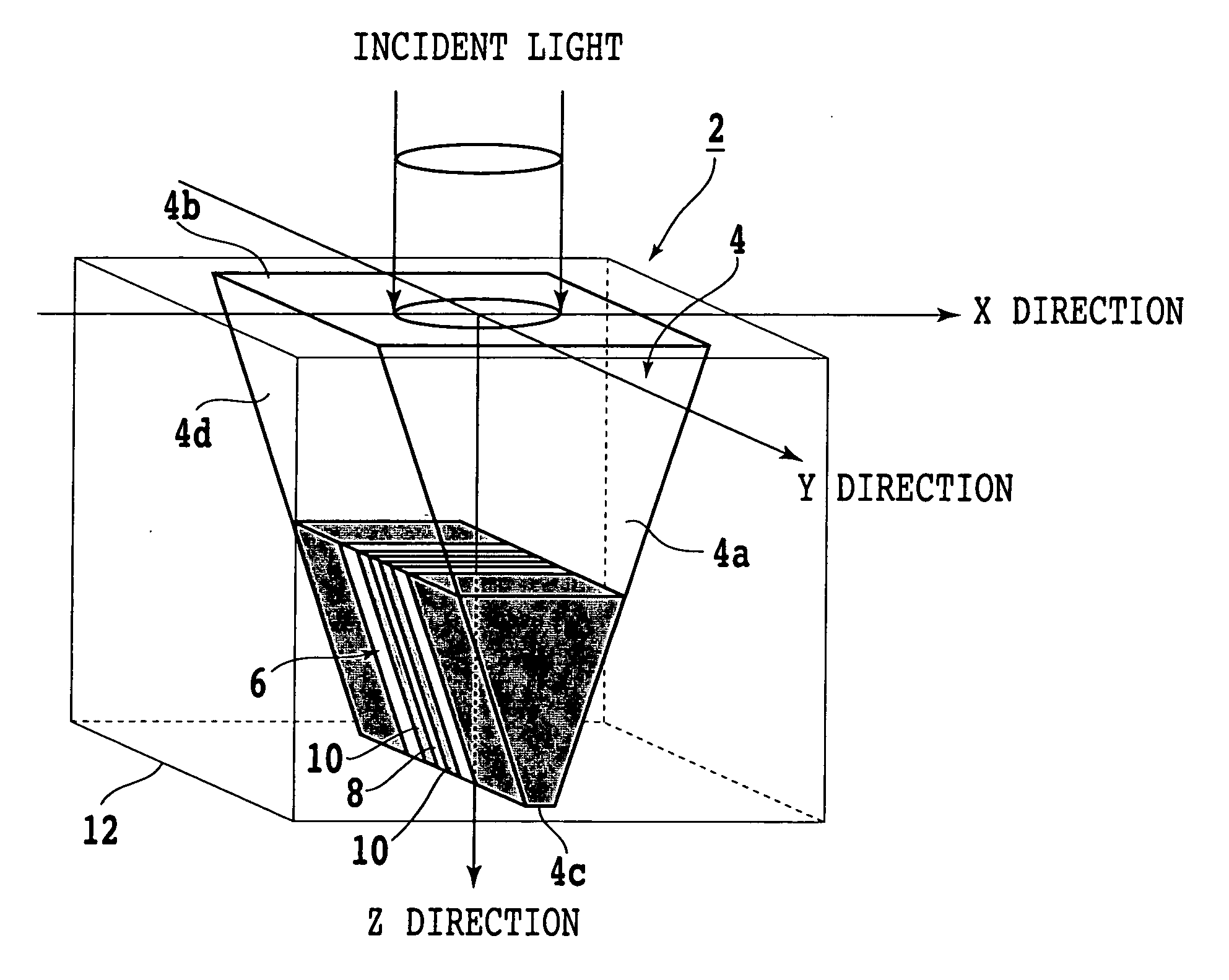
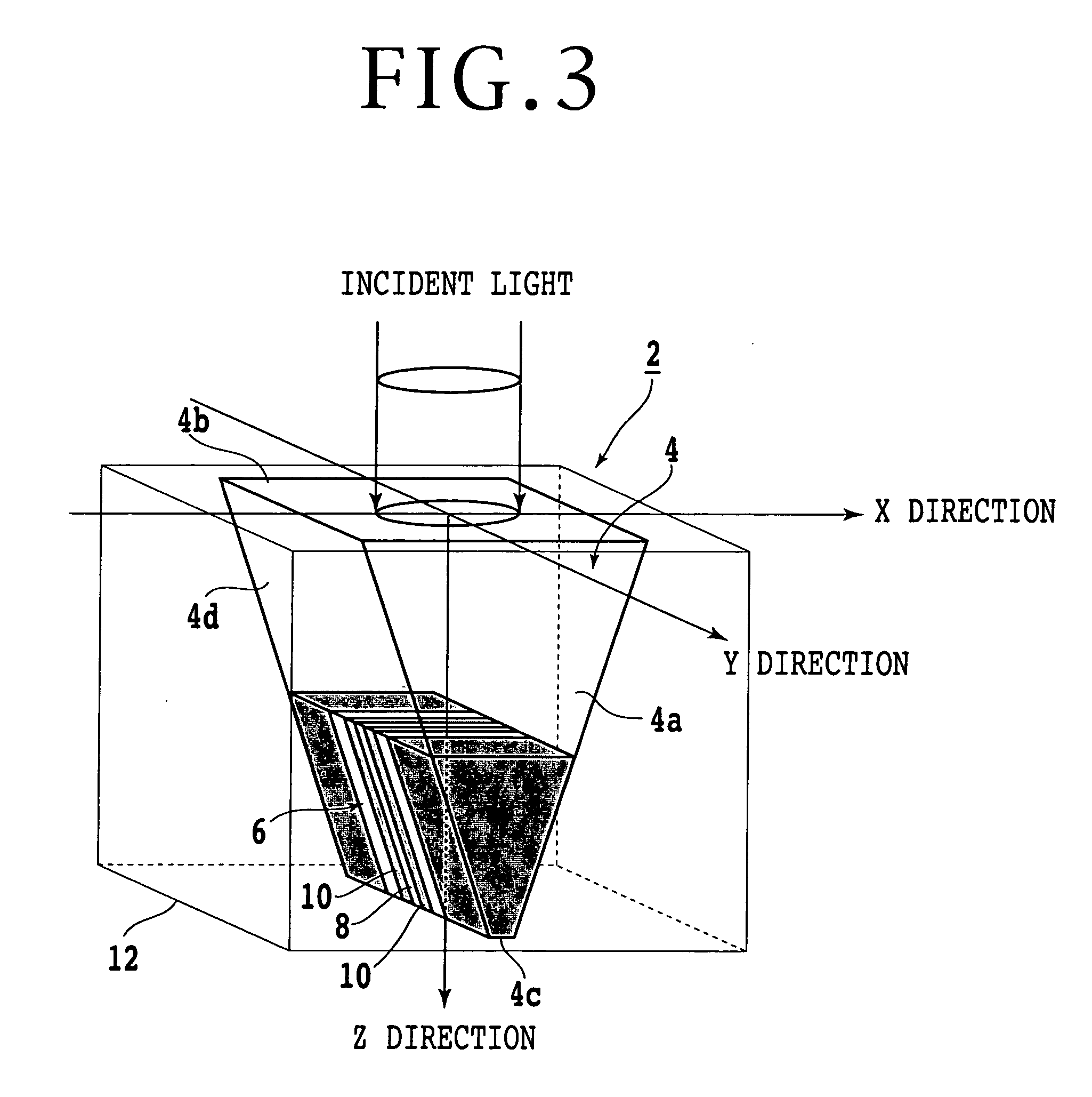
[0067] To generate minute light, it is considered to use a minute opening in two dimensions or use a single slit in one dimension. In the case that such an opening or slit has a size (e.g., about 100 nm) less than or equal to the wavelength of light, the light passing through the opening or slit is very weak. Under these circumstances, the present inventors have focused attention on periodically formed diffraction gratings. When the difference between a high refractive index and a low refractive index is very large, a specific behavior is sometimes exhibited to the transmission of light. However, the behavior of light under such a circumstance has not yet been investigated in detail. Attention has been paid to the use of wide-gap semiconductors in the III-V group, for example, as a material having a high refractive index.

[0068] In the case of a transmission type diffraction grating, when the length (pitch) of the period of diffraction gratings is larger than the wavelength of incid...


PUM


Abstract

An optical head including a first dielectric layer having a first refractive index, a pair of second dielectric layers located adjacent to the first dielectric layer on both sides thereof, each of the second dielectric layers having a second refractive index larger than the first refractive index, a pair of third dielectric layers located adjacent to the second dielectric layers, and a pair of fourth dielectric layers located adjacent to the third dielectric layers, each of the fourth dielectric layers having a third refractive index larger than the first refractive index. Light is incident on the optical head in a direction orthogonal to a layering direction of the first to fourth dielectric layers. The first dielectric layer and each of the third dielectric layers have different refractive indices or different thicknesses.

Description


Claims


Application Information

Patent Timeline
Owner FUJITSU LTD
Why Eureka
Try Eureka