Mirror support mechanism and optical apparatus using the same

Active Publication Date: 2005-07-21
MITSUBISHI ELECTRIC CORP
View PDF9 Cites 10 Cited by
  • Summary
  • Abstract
  • Description
  • Claims
  • Application Information

AI Technical Summary

Benefits of technology

[0009] Therefore, according to the present invention, the mirror is supported by the fluid pressure support mechanism and the electromagnetic attracting actuator. Hence, it is possible to increase the rigidity of the support mechanism and to expand the bandwidth of position control.
[0010] Further, according to the present invention, fluid tubes are connected to the containers of the fluid pressure support mechanisms so as to make all the fluid pressure support mechanisms communicate with each other. Therefore, it is possible to shorten the length of the fluid tubes and hence to reduce cost, and since the connection points of the fluid tubes are reduced in total number, it is possible to reduce connection errors and hence to improve ease of assembling and maintainability.
[0011] Still further, according to another aspect of the present invention, the container hav

Problems solved by technology

However, if an active driving mechanism is added to this passive structure and the main mirror or the individual mirror panels are intended to drive, there is presented a problem that the bandwidth of drive control cannot be maintained in wide area because of backlash in the mechanical parts in the support structure and the low rigidity of the support structure.
In additi

Method used


Image

  • Mirror support mechanism and optical apparatus using the same
  • Mirror support mechanism and optical apparatus using the same
  • Mirror support mechanism and optical apparatus using the same

Examples


embodiment 1

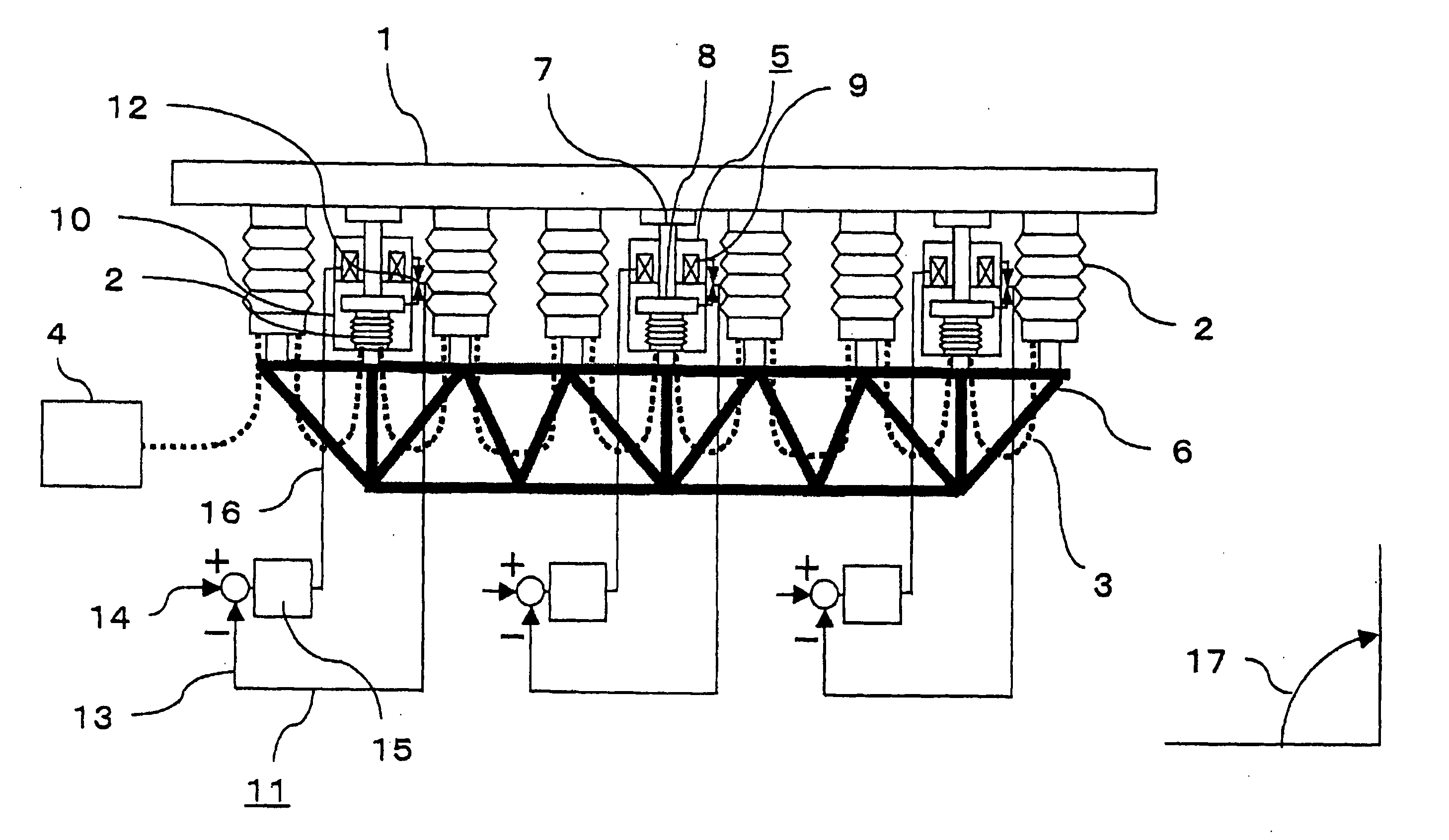
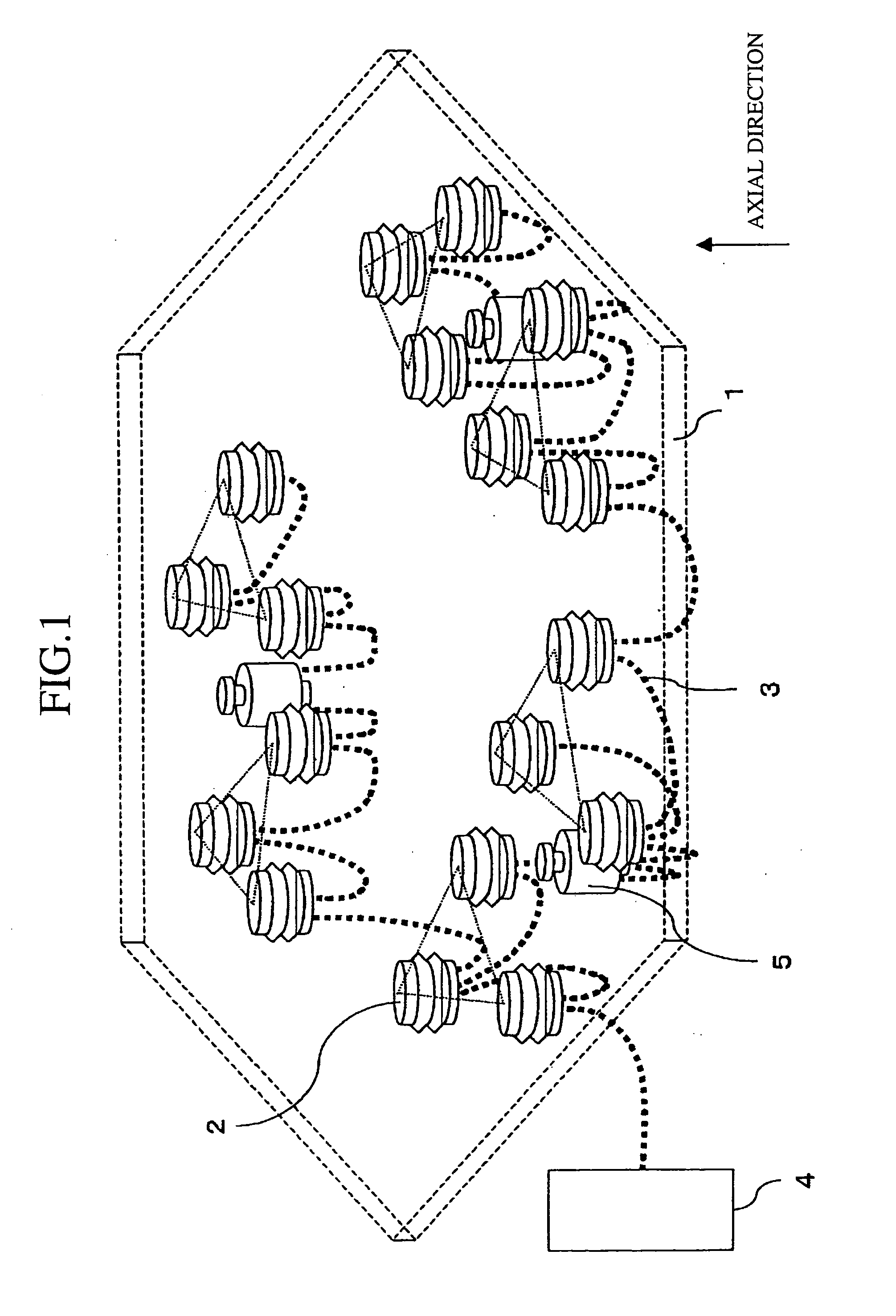
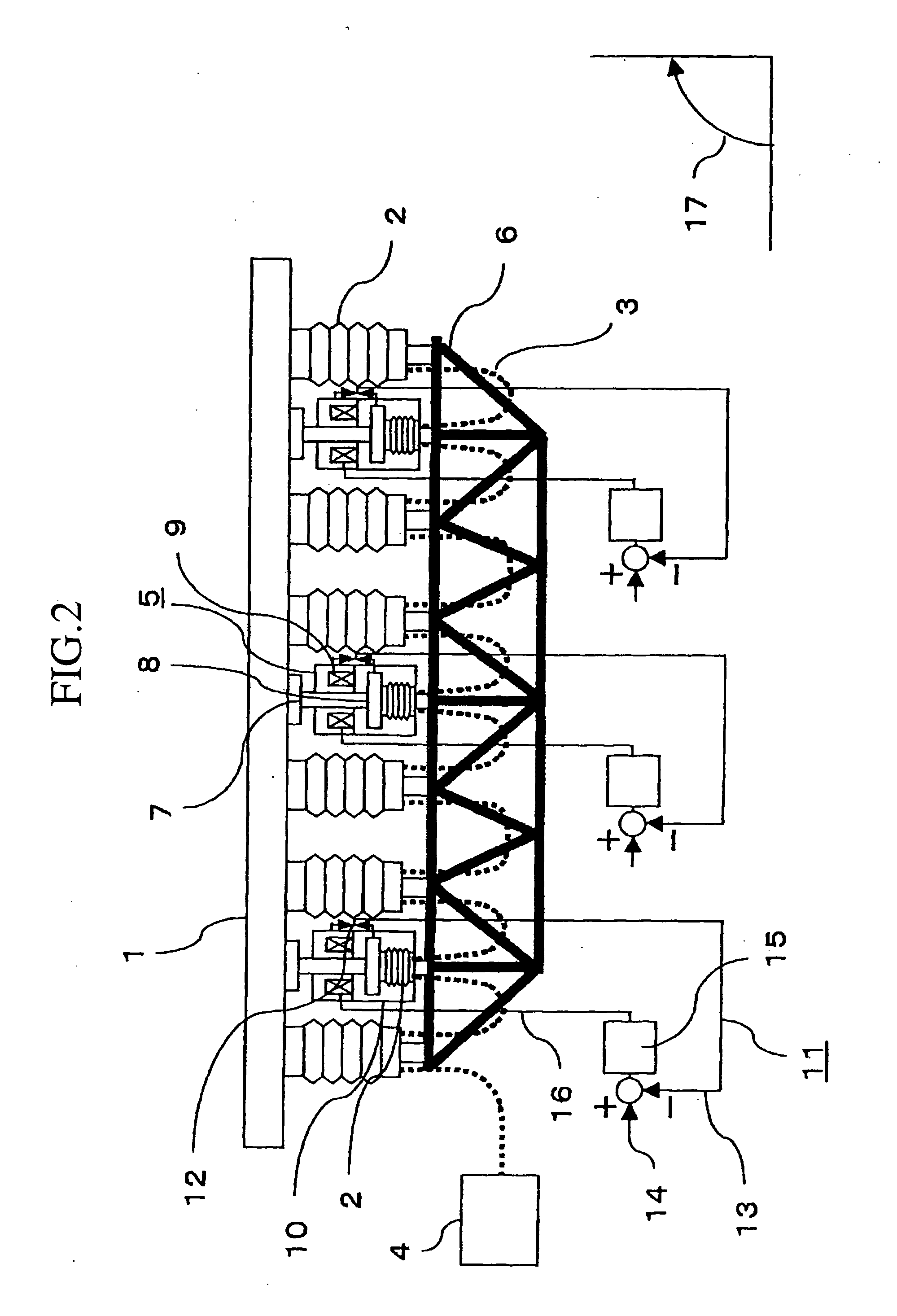
[0021] A mirror support mechanism in accordance with embodiment 1 of the present invention will be described on the basis of FIG. 1 and FIG. 2. FIG. 1 is a perspective view to show the structure of a mirror support mechanism in accordance with embodiment 1 of the present invention. FIG. 2 is a structure diagram of the mirror support mechanism in accordance with embodiment 1 of the present invention. In FIG. 1 is shown a mirror support mechanism provided with an actuator for supporting a single mirror in an axial direction and displacing the mirror as a rigid body. In FIG. 1, a reference numeral 1 denotes a mirror. Although the mirror is shown as a hexagonal mirror in the drawing, the mirror may be a mirror of any type such as circular mirror, square mirror, plane mirror, or curved mirror. A reference numeral 2 denotes a fluid pressure support mechanism for supporting the mirror 1 in the axial direction and the fluid pressure support mechanism 2 is connected to the mirror 1 at mounti...

embodiment 2

[0028]FIG. 3 is a structure diagram of a mirror support mechanism and an optical apparatus using the same in accordance with embodiment 2 of the present invention. In FIG. 3, a reference numeral 18 denotes a segment mirror in which a plurality of small size mirrors 1 are spread so as to produce a predetermined gap, thereby composing a mirror as if it were made of a single mirror, and a plurality of segment mirrors 18 are arranged to form an optical apparatus. Of course, the segment mirror 18 may be made of a single mirror in some cases. For example, as in the concept of a terrestrial telescope having a large caliber typified by CELT (California Extremely Large Telescope) and OWL (Overwhelmingly Large Telescope), there are cases where one thousand or more hexagonal segment mirrors 18 each having a diameter of about 1 m are spread. The segment mirror 18 is supported by the mirror cell 6 via the fluid pressure support mechanisms 2 and the electromagnetic attracting type actuators 5 in ...

embodiment 3

[0032] In the electromagnetic attracting type actuator 5 described in embodiment 1, the driven member 8 can be provided outside the casing 10. FIG. 4 is a structure diagram of a mirror support mechanism in accordance with embodiment 3 of the present invention. In embodiment 1, the driven member 8 is arranged opposite to the bottom surface of the electromagnet 9 in the casing 10 of electromagnetic attracting type actuator 5, but in embodiment 3, the driven member 8 is arranged at a position opposite to the top surface of electromagnet 9. The rod 7 which is connected to the mirror 1 is provided with the driven member 8 and the electromagnet 9 is arranged opposite to and below the driven member 8. The electromagnet 8 is held by the casing 10 and the casing 10 is fixed to the mirror cell 6. The gap sensor 12 is provided between the driven member 8 and the fixed side which are the casing 10 and the electromagnet 9. Further, the driven member 8 is passed through the center of electromagne...


PUM


Abstract

A fluid pressure support mechanism has a container in which fluid pressure is applied and fluid tubes are connected to the fluid pressure support mechanisms and to a fluid pressure control unit in such a way as to make all the fluid pressure support mechanisms communicate with each other, then a fluid pressure control unit applies the fluid pressure to the containers in the respective fluid pressure support mechanisms via the fluid tubes and controls the fluid pressure, and an electrically attractive actuator translates a mirror in an axial direction with one degree of freedom for translation by attracting force produced by a driven member and an electromagnet.

Description

BACKGROUND OF THE INVENTION [0001] 1. Field of the Invention [0002] The present invention relates to a mirror support mechanism that supports a mirror integrated in a telescope in such a way as to prevent a mirror surface accuracy from being degraded by the deformation of the mirror, and an optical apparatus using the same. [0003] 2. Description of the Related Art [0004] A mirror support mechanism in a conventional telescope is described in a non-patent document 1. According to FIG. 4. 24 (page 290) and description corresponding to the drawing in this non-patent document 1, a whiffle-tree support mechanism is disclosed as a support in the axial direction of a main mirror. In this whiffle-tree support mechanism, spherical seats are provided at three fixed points and a trifurcate pole is placed on each of these spherical seats and nine pads of the main mirror are placed on the top of the trifurcate pole via spherical seats. The trifurcate pole is made freely incline along the back of ...

Claims


Application Information

Patent Timeline
IPC IPC(8): G02B23/02F15B15/10F15B15/28G02B7/182G02B7/183G02B7/198
CPCG02B7/183
Inventor OSHIMA, TAKEHARUITO, NOBORU
Owner MITSUBISHI ELECTRIC CORP
Why Eureka
Try Eureka