Total disc replacement system and related methods

a total disc and disc technology, applied in the field of spinal surgery, can solve the problems of total disc replacement system, dislocation of anchor plates from vertebral end plates, over-distraction of vertebral end plates, etc., and achieve the effect of facilitating the introduction of intradiscal elements

Inactive Publication Date: 2005-07-21
NUVASIVE
View PDF11 Cites 224 Cited by
  • Summary
  • Abstract
  • Description
  • Claims
  • Application Information

AI Technical Summary

Benefits of technology

[0010] The semi-cylindrical articular surface of the first and / or second anchor plates may be generally concave and / or generally convex. The generally arcuate cross-sections of the first and / or second articular surfaces of the intradiscal element may be generally concave and / or convex. The second surface of the first and / or second anchor plates may include a ramped portion to facilitate the introduction of the intradiscal element into articulating engagement with the semi-cylindrical articular surfaces of the first and second anchor plates. The intradiscal element may be prevented from translating relative to the first and / or second anchor plates.

Problems solved by technology

Known total disc replacement systems suffer disadvantages including the dislocation of the anchor plates from the vertebral end plates, over-distraction of the vertebral endplates during introduction, particulate wear and debris of the component parts, and a lack of conformity between the anchor plates and the internal components during use.

Method used


Image

  • Total disc replacement system and related methods
  • Total disc replacement system and related methods
  • Total disc replacement system and related methods

Examples


first embodiment

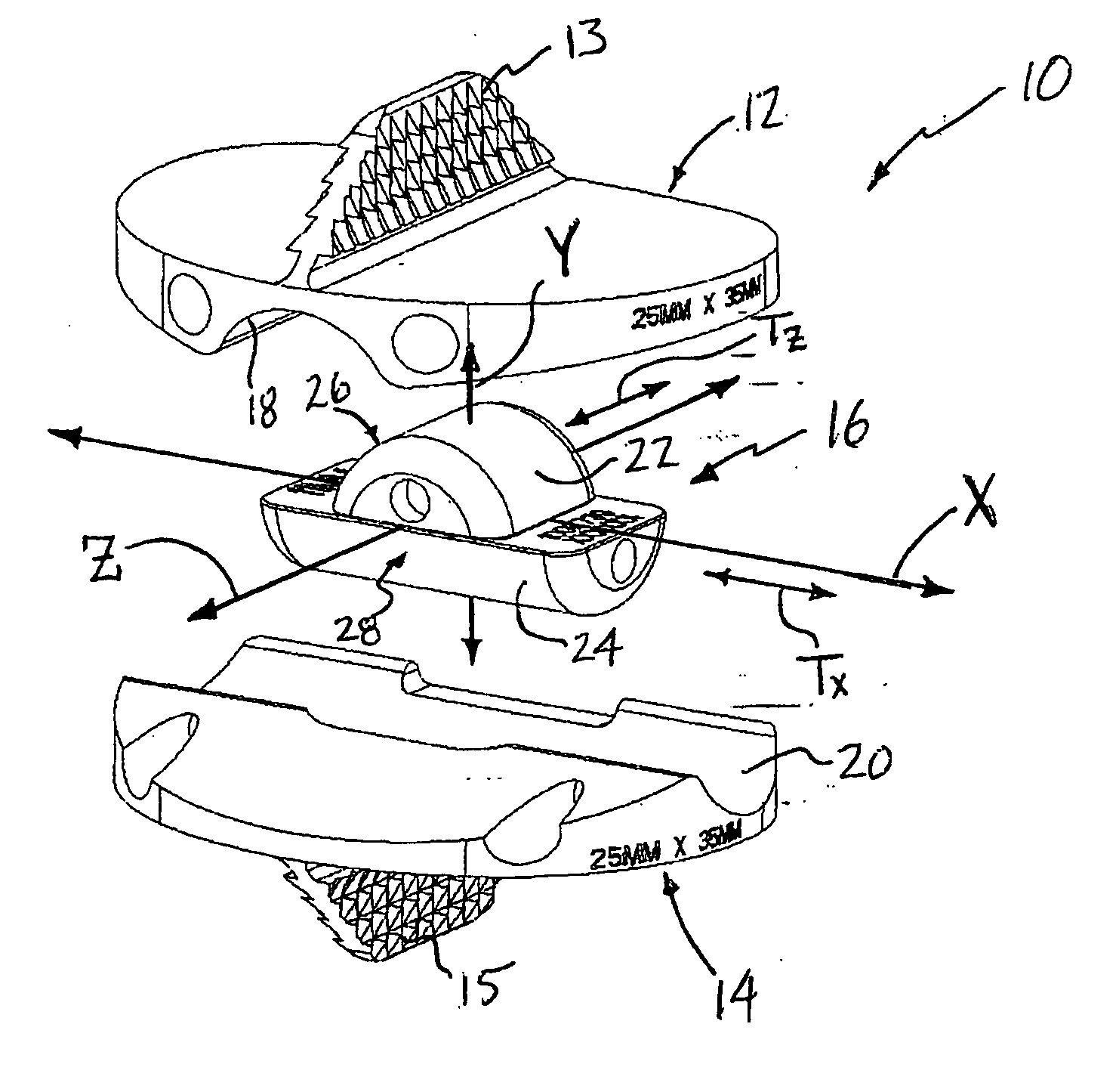
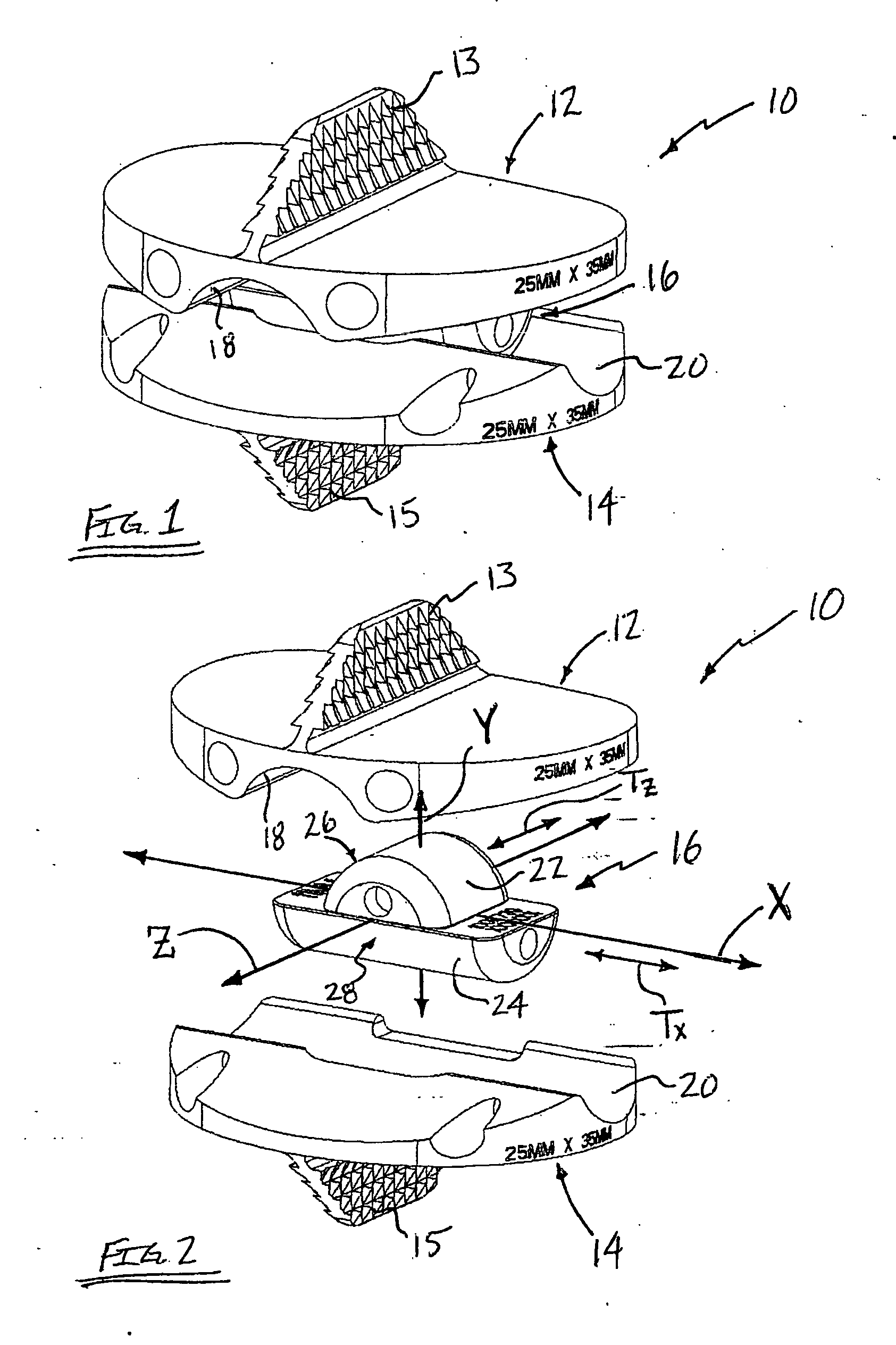
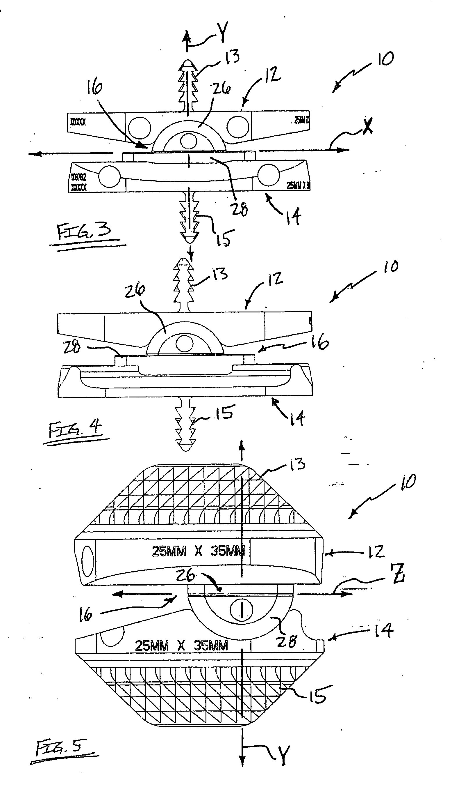
[0046] In addition to the rotational capability about the Y-axis, the first articular surface 22 is dimensioned to articulate with the semi-cylindrical articular surface 18 of the first anchor plate 12, while the second articular surface 24 is dimensioned to articulate with the semi-cylindrical articular surface 20 of the second anchor plate 14. This enables the first anchor plate 12 to rotate relative to the intradiscal element 16 about the Z-axis, and the second anchor plate 14 may rotate relative to the intradiscal element 16 about the X-axis. As noted above, this also enables the first anchor plate 12 to translate relative to the intradiscal element 16 in either direction along the Z-axis, and the second anchor plate 14 to translate relative to the intradiscal element 16 in either direction along the X-axis. In this fashion, the TDR system 10 of this first embodiment provides rotation along three distinct axes (X, Y, Z) and translation along two distinct axes (X and Z).

[0047] Th...

second embodiment

[0048]FIGS. 24-36 illustrate a total disc replacement (TDR) system 110 according to the present invention. The TDR system 110 is designed to operate in the same fashion as the TDR system 10 shown and described above, except that the TDR system 110 is particularly suited for lateral and / or minimal access introduction into the spine. (For the sake of clarity, all features or components in common with the TDR system 10 will be numbered “+100” and, as to those features, reference can be made to the discussion above regarding the TDR system 10, rendering a repeat discussion unnecessary and optional). To accomplish this, as best viewed respectively in FIGS. 31 and 35, the first and second anchor plates 112, 114 each have a generally rectangular shape including a width of less than 25 mm. Dimensioning the first and second anchor plates 112, 114 in this fashion advantageously provides the ability to advance the TDR system 110 through a minimal access surgical corridor. It also advantageousl...


PUM


Abstract

A total disc replacement (TDR) system for use in the spine and related methods, involving a first anchor plate having a first surface for engaging a first vertebra and a second surface including a semi-cylindrical articular surface, a second anchor plate having a first surface for engaging a second vertebra and a second surface including a semi-cylindrical articular surface, and an intradiscal element including a first articular surface having a generally arcuate cross-section for articulating with said semi-cylindrical articular surface of said first anchor plate, and a second articular surface having a generally arcuate cross-section for articulating with said semi-cylindrical articular surface of said second anchor plate.

Description

CROSS-REFERENCES TO RELATED APPLICATIONS [0001] This application is a continuation under 35 U.S.C. 111(a) of PCT Patent Application Serial No. PCT / U.S. 2003 / 20333, filed Jun. 26, 2003 and published on Jan. 8, 2004 as WO 2004 / 002291 A2 which is incorporated herein by reference. [0002] The present application also claims the benefit of priority from U.S. Provisional Patent Application Ser. No. 60 / 392,206 (filed Jun. 26, 2002), the entire content of which is hereby expressly incorporated by reference into this disclosure as if set forth fully herein.BACKGROUND OF THE INVENTION [0003] I. Field of the Invention [0004] The present invention relates generally to spinal surgery and, more particularly, to total disc replacement systems and related methods. [0005] II. Description of Related Art [0006] In recent years, the area of total disc replacement has experienced proliferated growth and attention from the medical community. Known total disc replacement devices generally require some form...

Claims


Application Information

Patent Timeline
Patent Type & Authority Applications(United States)
IPC IPC(8): A61F2/00A61F2/30A61F2/44A61F2/46
CPCA61F2/4425A61F2310/00239A61F2002/30153A61F2002/30232A61F2002/30242A61F2002/30332A61F2002/30364A61F2002/30392A61F2002/30393A61F2002/30398A61F2002/304A61F2002/30497A61F2002/30604A61F2002/30635A61F2002/30878A61F2002/30884A61F2002/443A61F2220/0025A61F2220/0033A61F2230/0019A61F2230/0069A61F2230/0071A61F2310/00029A61F2310/00203A61F2/4611A61F2002/30495
Inventor BLAIN, JASON
Owner NUVASIVE
Why Eureka
Try Eureka