Tandem compressors with economized operation

a technology of tandem compressors and compressors, which is applied in the direction of refrigeration components, mechanical equipment, lighting and heating equipment, etc., to achieve the effect of reducing costs

Active Publication Date: 2005-07-28
CARRIER CORP
View PDF10 Cites 17 Cited by
  • Summary
  • Abstract
  • Description
  • Claims
  • Application Information

AI Technical Summary

Benefits of technology

[0005] In an alternative embodiment, it may be that only one of the two economizer return lines is provided with a shutoff valve, and a main economizer shutoff valve is placed on the common economizer manifold. In this embodiment, one of the two tandem compressors is selected to be initially moved out of economizer operation in a preferential manner. This would be the compressor with the shutoff valve on its individual economizer return line. In a lower cost alternative, only the economizer manifold includes the shutoff valve.
[0006] Further, in a lower cost embodiment, a single unloader valve may communicate each of the economizer lines back to suction or pressure equalization line. By connecting the unloader line to the economizer line, refrigerant can be effectively tapped from the intermediate compression chambers back to suction when the economizer shutoff valves are closed.

Problems solved by technology

Although economizer circuits provide additional benefits to a refrigerant cycle as described above, they have not been incorporated into refrigerant cycles having tandem compressors.

Method used


Image

  • Tandem compressors with economized operation
  • Tandem compressors with economized operation

Examples


Embodiment Construction

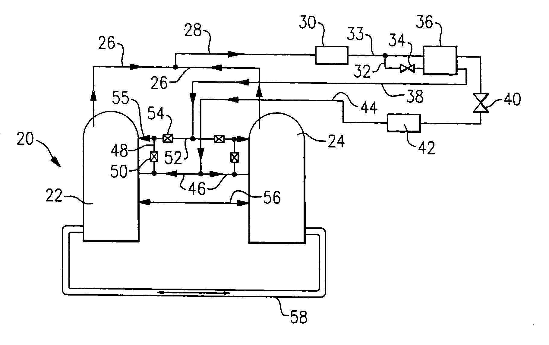
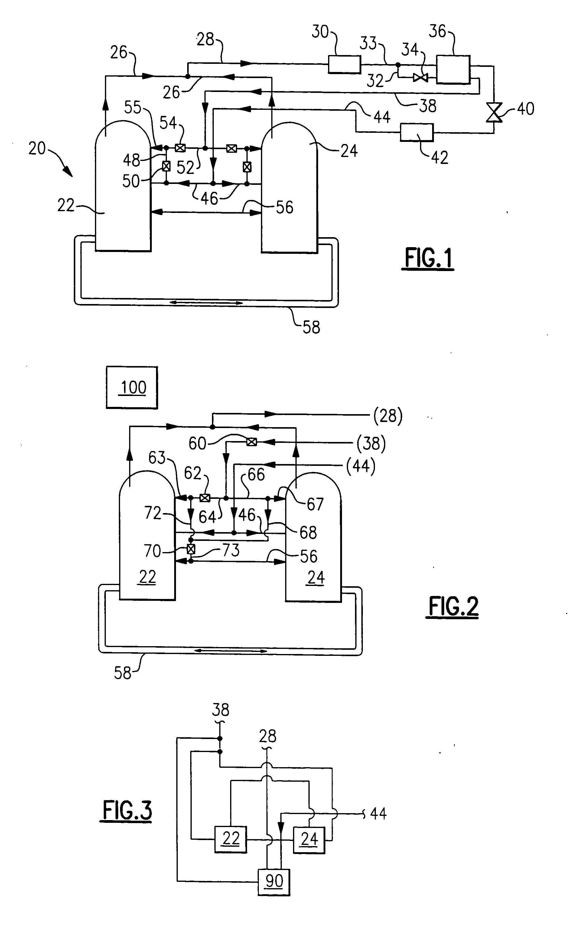
[0012]FIG. 1 shows a refrigerant cycle 20 having tandem compressors 22 and 24. Compressors 22 and 24 communicate compressed refrigerant into individual discharge lines 26 leading to a common discharge manifold 28. Downstream of discharge manifold 28, the refrigerant is delivered to a condenser 30.

[0013] An economizer tap 32 taps off of a main refrigerant line 33, downstream of condenser 30. As shown, an economizer expansion device 34 is placed on the tap line 32 upstream of an economizer heat exchanger 36. The tap line 32 and the main refrigerant flow line 33 both pass through the economizer heat exchanger 36, as known. In practice, it is preferred that the refrigerant in the tapped refrigerant line 32 move in a counter-flow relationship to the main refrigerant flow in line 33, rather than moving in the same direction as illustrated. However, for simplicity of illustration, the flows are shown in the same direction. As is known, the main refrigerant flow 33 is cooled in the economi...


PUM


Abstract

A refrigerant cycle includes economized tandem compressors. The refrigerant cycle is also provided with a common economizer circuit for all tandem compressors. Common manifolds communicate discharge, suction and economizer return flows within the refrigerant cycle to each of the tandem compressors. Also, an optional unloader function is provided for each of the compressors. Various arrangements allow enhanced operation control, improved system reliability and reduced equipment life-cycle cost.

Description

BACKGROUND OF THE INVENTION [0001] This invention relates to a refrigerant cycle having tandem compressors, wherein the tandem compressors are each provided with an economizer port and can operate within an economizer cycle. [0002] Tandem compressor refrigerant cycles are known, and have two or more compressors compressing refrigerant and delivering it to a common discharge manifold. Similarly, these compressors are drawing refrigerant from a common suction manifold. In some arrangements, oil equalization lines connecting oil sumps of tandem compressors for oil management, and suction pressure equalization lines connecting shells of the tandem compressors are employed. The tandem compressors provide flexibility to a refrigerant cycle designer, such as allowing additional levels of capacity control by turning off some of the compressors. Moreover, in some applications that would otherwise require a very large single compressor, the tandem compressors provide design options, availabil...

Claims


Application Information

Patent Timeline
Patent Type & Authority Applications(United States)
IPC IPC(8): F25B1/10F25B41/04
CPCF25B1/10F25B41/04F25B2600/0261F25B2400/13F25B2400/075F25B41/20F25B41/24
Inventor TARAS, MICHAEL F.LIFSON, ALEXANDERDOBMEIER, THOMAS J.
Owner CARRIER CORP
Why Eureka
Try Eureka