AI technical title is built by Patsnap AI team. It summarizes the technical point description of the patent document.
a technology of projector and zoom, applied in the field of projector, can solve problems such as impeded writing
Inactive Publication Date: 2005-07-28
SEIKO EPSON CORP
View PDF8 Cites 29 Cited by
Summary
Abstract
Description
Claims
Application Information
AI Technical Summary
This helps you quickly interpret patents by identifying the three key elements:
Problems solved by technology
Method used
Benefits of technology
Benefits of technology
[0009] The present invention was developed in order to solve the above-stated problems. The purpose of the present invention is to provide an automatic method of zoom adjustment in which the projection region becomes accommodated within the object of projection without requiring the attachment of markers, etc. onto the object of projection, and in which the projected image displayed onto the object of projection is rendered sufficiently large for the object of projection.
Problems solved by technology
In particular regards to portable projectors, it is possible for the distance from the object of projection to become varied every time they are set up; therefore, it has been necessary for the above-stated zoom adjustment to be conducted each time, which has been cumbersome.
Moreover, such markers may be attached to the white board on a normal basis; however, in such cases, when writing on the board, such markers have impeded writing, which is problematic.
Method used
Image
Click on the blue label to locate the original text in one second.
Reading with bidirectional positioning of images and text.
Examples
embodiment
A. Embodiment
[0050] A1. First Embodiment: [0051] A1-1. Structure of the zoom device: [0052] A1-2. Specific actions of the zoom adjustment: [0053] A1-3. Effects of the first embodiment:
A2. Second Embodiment: [0054] A2-1. Purpose of the zoom adjustment: [0055] A2-2. Specific actions of the zoom adjustment: [0056] A2-3. Detailed actions of the vertex block detection treatment: [0057] A2-4. Effects of the second embodiment:
A. Modification Examples:
[0058] B1. Modification Example #1:
[0059] B2. Modification Example #2:
[0060] B3. Modification Example #3:
[0061] B4. Modification Example #4:
[0062] B5. Modification Example #5:
[0063] B6. Modification Example #6:
[0064] B7. Modification Example #7:
[0065] B8. Modification Example #8:
A. Embodiment:
[0066] A1. First Embodiment:
[0067] A1-1. Structure of the zoom device:
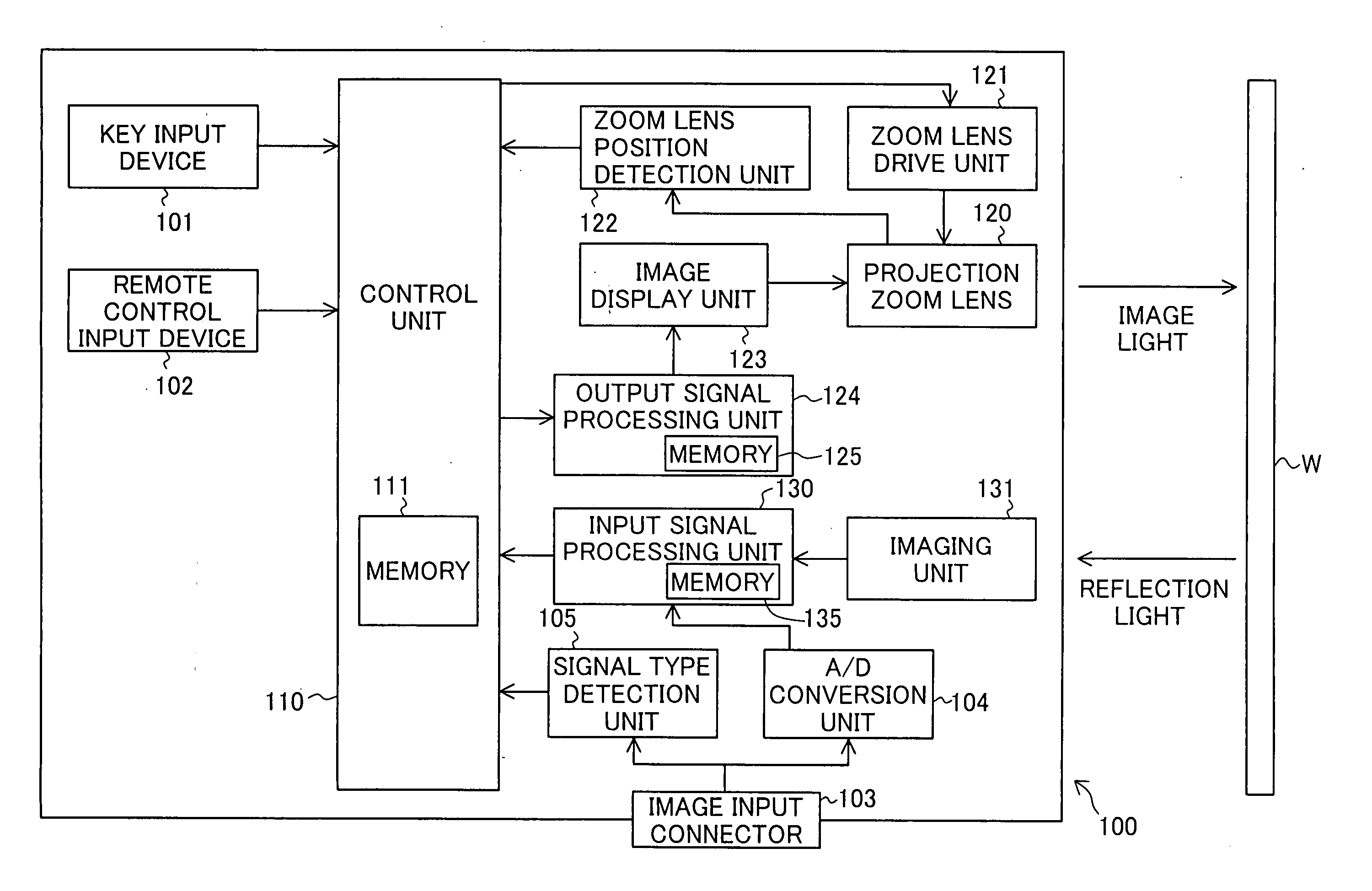
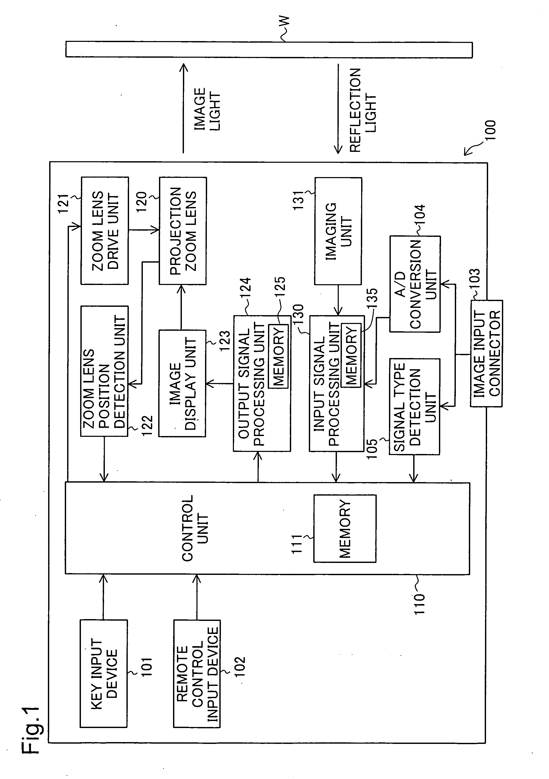
[0068] First of all, the schematic structure of the projector in one embodiment of the present invention is explained, utilizing FIG. 1 as a reference.
[0069]FIG. 1 is ...
second embodiment
A2.
[0130] A2-1. Purpose of the zoom adjustment:
[0131] In the present embodiment, an explanation is given regarding the zoom adjustment, the purpose of which is to render the reflection region sufficiently large for the object of projection in consideration of keystone correction.
[0132] In addition, the structure of the projector of the present embodiment is the same as that of the Projector 100 shown in FIG. 3.; therefore, its explanation is omitted. Furthermore, the test pattern images below are similar to those of the first embodiment.
[0133] First of all, an explanation is given regarding the purpose of this zoom adjustment, utilizing FIG. 4. FIGS. 4(A) and (B) are illustrations showing the state in which the image light is projected before and after keystone correction. In FIG. 4(A) shows the state in which the image light is projected prior to keystone correction; (B) shows the state in which the image light is projected after the keystone correction in the state of (A). In F...
modification examples
B. Modification Examples
[0189] The above embodiment and its application are to be considered in all aspects as illustrative and not restrictive. There may be many modifications, changes, and alterations without departing from the scope or spirit of the main characteristics of the present invention. Some examples of possible modification are given below.
PUM
Abstract
Traditionally, in the case in which an image is projected onto an object of projection not equipped with frame marking edges, markers have had to be attached to the object of projection each time in order to automatically adjust the size of the projection region to which the image light is projected, which was cumbersome. Thus, in the present invention, in projecting the test pattern images onto the object of projection, the zoomprojection lens is adjusted to enlarge the size of the projection region gradually, and the projection region is imaged each time. After the vertex of the object of projection matches the edge of the object of projection, when the projection region becomes forced out from the area of the object of projection, a part of the contour of the test pattern images projected within the imaged image matches a part of the edges of the object of projection. Therefore, the contours of the test pattern images projected within the projected images are compared before and after the enlargement. In the case in which there is a consistent portion, it is determined that the projection region has become forced out from the area of the object of projection, and an attempt is made to restore the size of the projection region to the previous size before the enlargement.
Description
BACKGROUND OF THE INVENTION [0001] 1. Field of the Invention [0002] The present invention relates to a projector, especially to a technology which automatically zooms onto a region to which image light is projected in consideration of the size of the object of projection. [0003] 2. Description of the Related Art [0004] Generally speaking, in utilizing a projector which projects an image onto the object of projection as image light, adjustment is conducted in a manner in which the region (hereafter, referred to as the “projection region) to which the image light is projected becomes completely accommodated within the object of projection, and in which the projected image that is projected (hereafter, referred to as the “projected image”) is displayed as large as possible. In addition, in many cases, such adjustment is conducted by means of adjusting the positions of the lens equipped in the projector as the projection lens (hereafter, referred to as the “zoom adjustment”). In particu...
Claims
Application Information
Patent Timeline
Application Date:The date an application was filed.
Publication Date:The date a patent or application was officially published.
First Publication Date:The earliest publication date of a patent with the same application number.
Issue Date:Publication date of the patent grant document.
PCT Entry Date:The Entry date of PCT National Phase.
Estimated Expiry Date:The statutory expiry date of a patent right according to the Patent Law, and it is the longest term of protection that the patent right can achieve without the termination of the patent right due to other reasons(Term extension factor has been taken into account ).
Invalid Date:Actual expiry date is based on effective date or publication date of legal transaction data of invalid patent.

