Pixel-shifting projection lens assembly to provide optical interlacing for increased addressability

a technology of projection lens and optical interlacing, which is applied in the field of projection lens assembly, can solve the problems of introducing defects relating to differences in the propagation angle of light being projected toward different portions of the display screen, affecting the accuracy of projection, so as to reduce the difficulty of manipulating a pixel-shifting elemen

Inactive Publication Date: 2005-06-23
3M INNOVATIVE PROPERTIES CO
View PDF55 Cites 82 Cited by
  • Summary
  • Abstract
  • Description
  • Claims
  • Application Information

AI Technical Summary

Benefits of technology

[0008] The projection lens assembly with a pixel-shifting element included among the lens elements can often provide resolutions that are at least twice the actual resolution of the pixelated display device. In addition, the optical space within the projection lens is typically significantly less susceptible to introdu

Problems solved by technology

Although there are many advantages of these pixelated displays, they can also bring with them the disadvantage of fixed and relatively coarse addressability.
Another problem is that each picture element in some pixelated displays includes a central imaging area or aperture that transmits or reflects image information and is bounded by an opaque border.
While providing in-fill pixel scanning both of the implementations can suffer from disadvantages relating to maintaining optimal image clarity.
Shifting pixel locations in such a diverging optical space can introduce defects relating

Method used


Image

  • Pixel-shifting projection lens assembly to provide optical interlacing for increased addressability
  • Pixel-shifting projection lens assembly to provide optical interlacing for increased addressability
  • Pixel-shifting projection lens assembly to provide optical interlacing for increased addressability

Examples


Embodiment Construction

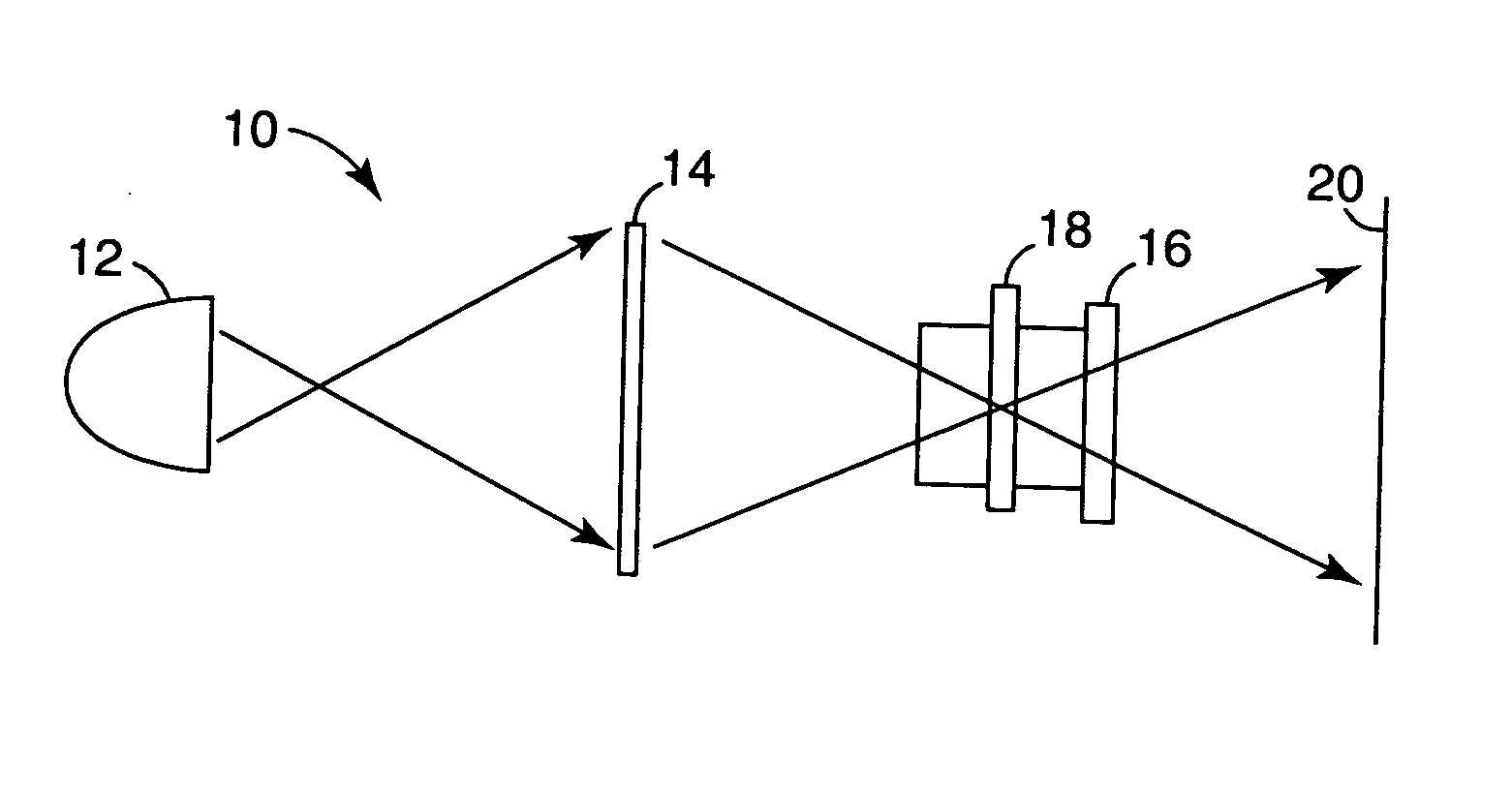
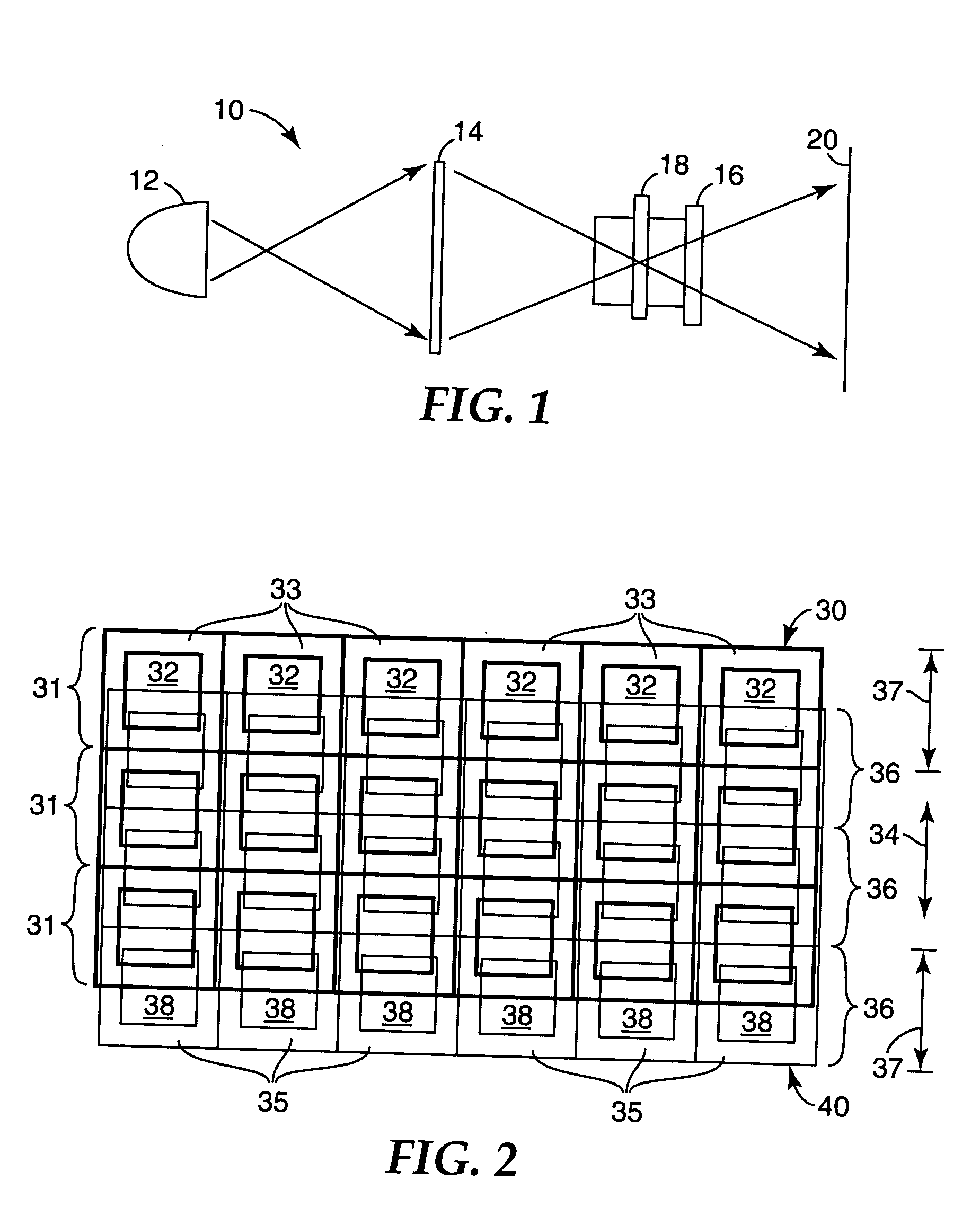
[0022]FIG. 1 is a schematic side view of a projection display system 10 employing pixel-shifting optical interlace for increased pixel addressability according to the present invention. Projection system10 includes an illumination system 12, a pixelated display device 14, and a multi-lens projection lens assembly 16 with a pixel-shifting element 18. It will be appreciated that the schematic representation of FIG. 1 does not show various conventional optical elements as are known in the art of projection displays.

[0023] Illumination system 12 directs illumination light at pixelated display device 14, which imparts display information on the illumination light in any conventional or similar manner. Pixelated display device 14 may include a liquid crystal display, a digital micromirror device, or any other type of pixelated display device. Illumination light may be transmitted through pixelated display device 14 as illustrated or may alternatively be reflected from it. Projection lens...


PUM


Abstract

A projection display system includes a projection lens assembly that has multiple projection lens elements that are configured to receive light imparted with display information by a pixelated display device. The projection lens elements project the light toward a display screen. A pixel-shifting element is included within the projection lens assembly to cyclically shift between at least two positions within the projection lens assembly to form at a display screen at least two interlaced arrays of pixels. An electromechanical transducer is coupled to the pixel-shifting element to impart on it the cyclic shifting between positions.

Description

TECHNICAL FIELD [0001] The present invention relates to projection lens assemblies for projection display systems and, in particular, to a projection lens assembly that includes a pixel-shifting element to provide optical interlacing of pixels for increased addressability. BACKGROUND OF THE INVENTION [0002] In many types of display systems images are formed by pixelated optical modulators such as conventional liquid crystal displays, digital micromirror devices, liquid crystal-on-silicon modulators, etc. Although there are many advantages of these pixelated displays, they can also bring with them the disadvantage of fixed and relatively coarse addressability. Resolution relates to the number of pixels in a pixelated display panel, and addressability relates to the number of pixel locations in a display image (i.e., the display panel resolution times the number of distinct positions that each pixel can occupy in a display image). [0003] Another problem is that each picture element in...

Claims


Application Information

Patent Timeline
IPC IPC(8): H04N9/31
CPCH04N9/3197H04N9/3188G02B27/18G03B21/00H04N5/74
Inventor CONNER, ARLIE R.KINGSLEY, GARY B.
Owner 3M INNOVATIVE PROPERTIES CO
Why Eureka
Try Eureka