

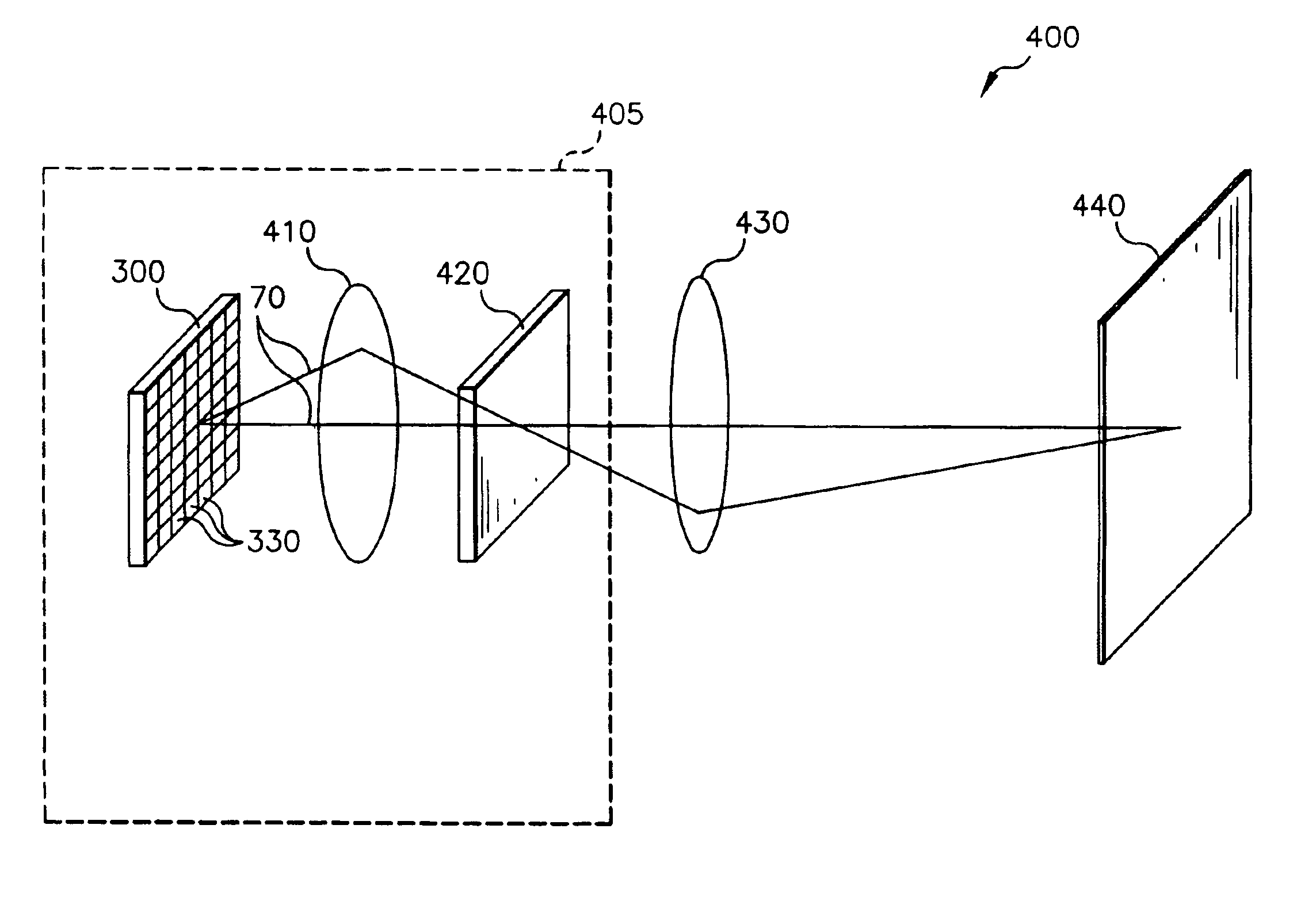
Electronic imaging system using organic laser array illuminating an area light valve
an electronic imaging system and laser array technology, applied in the field of electronic imaging systems, can solve the problems of hampered development of electronic imaging systems using light valves, lack of low-cost visible lasers suitable for electronic imaging systems, and insufficient power of lasers at appropriate visible wavelengths. , to achieve the effect of suppressing laser speckle, reducing flare, and improving image uniformity
- Summary
- Abstract
- Description
- Claims
- Application Information
AI Technical Summary
Benefits of technology
Problems solved by technology
Method used
Image

Examples
Embodiment Construction
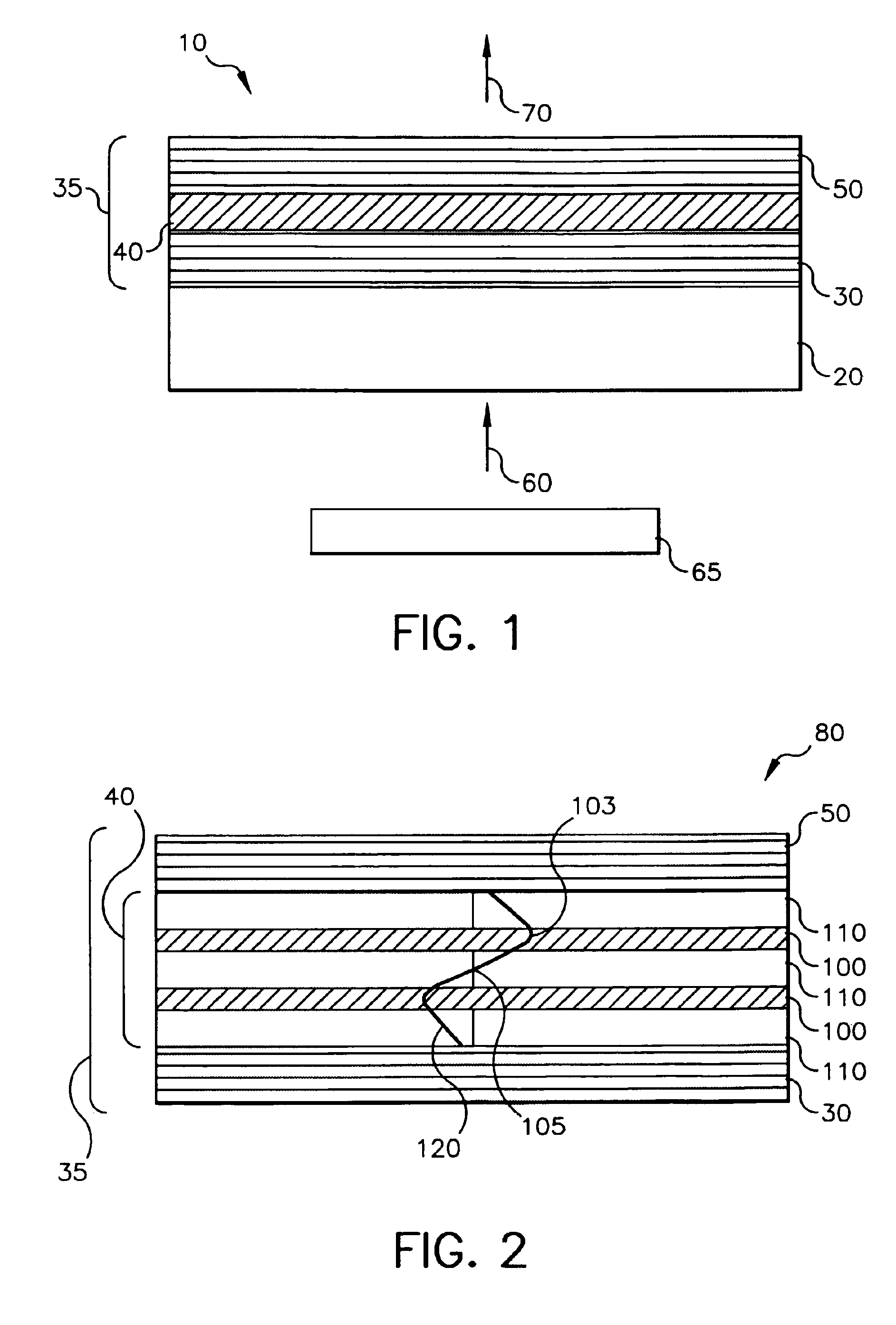
[0036]A schematic of a vertical cavity organic laser device 10 is shown in FIG. 1. The substrate 20 can either be light transmissive or opaque, depending on the intended direction of optical pumping and laser emission. Light transmissive substrates 20 may be transparent glass, plastic, or other transparent materials such as sapphire. Alternatively, opaque substrates including, but not limited to, semiconductor material (e.g. silicon) or ceramic material may be used in the case where both optical pumping and emission occur through the same surface. On the substrate is deposited an organic laser film structure 35, which comprises a first dielectric stack 30 followed by an organic active region 40 and a second dielectric stack 50. A pump beam 60, emitted from a source of photons 65, optically pumps the vertical cavity organic laser device 10 through the first dielectric stack 30, which is substantially transmissive for the pump beam 60. The second dielectric stack 50 should be substant...
PUM
| Property | Measurement | Unit |
|---|---|---|
| power | aaaaa | aaaaa |
| frequencies | aaaaa | aaaaa |
| internal quantum efficiency | aaaaa | aaaaa |
Abstract
Description
Claims
Application Information