Radiological image detection apparatus

a detection apparatus and radiation image technology, applied in the direction of x/gamma/cosmic radiation measurement, radioation controlled devices, instruments, etc., can solve the problems of local degrading the sharpness of images, reducing the etc., and achieving the effect of improving uniformity of image quality and being easy to separate from each other

Active Publication Date: 2016-02-09
FUJIFILM CORP
View PDF31 Cites 6 Cited by
  • Summary
  • Abstract
  • Description
  • Claims
  • Application Information

AI Technical Summary

Benefits of technology

[0010]The present invention has been made in consideration of the above-mentioned matters, and it is an object of the present invention to provide a radiological image detection apparatus which has an excellent uniformity of image quality.
[0012]According to an aspect of the present invention, a scintillator and a pixel array are placed in a space formed by a first substrate for supporting the scintillator, a second substrate for supporting the pixel array, and a sealant, and the space is depressurized, such that the scintillator comes into close contact with the pixel array without being bonded to the pixel array. By forming both of the first substrate and the second substrate to be flexible, the scintillator and the pixel array may come into close contact with each other in its entirety without any gap. Therefore, the uniformity of the image quality can be improved.
[0013]Since the scintillator and the pixel array are not bonded to each other, the radiological image conversion panel and the sensor panel can be easily separated from each other. Therefore, when one of the radiological image conversion panel and the sensor panel is damaged, only the damaged panel can be replaced to recycle the panels as a radiological image detection apparatus.

Problems solved by technology

Therefore, the non-uniformity of image quality caused by the non-uniformity of the thickness of the adhesive layer is reduced.
The gap causes the diffusion of fluorescence generated from the scintillator, which may locally degrade the sharpness of an image.
Therefore, when one of the radiological image conversion panel and the sensor panel is damaged, only the damaged panel can be replaced to recycle the panels as a radiological image detection apparatus.

Method used


Image

  • Radiological image detection apparatus
  • Radiological image detection apparatus
  • Radiological image detection apparatus

Examples


Embodiment Construction

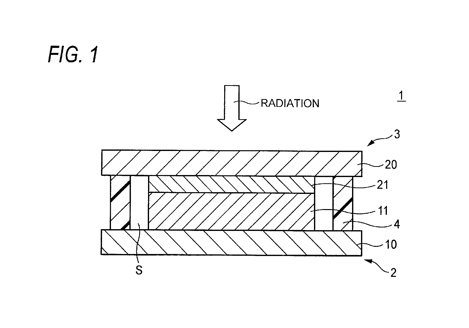
[0026]FIG. 1 illustrates a configuration of a radiological image detection apparatus according to an exemplary embodiment of the present invention.

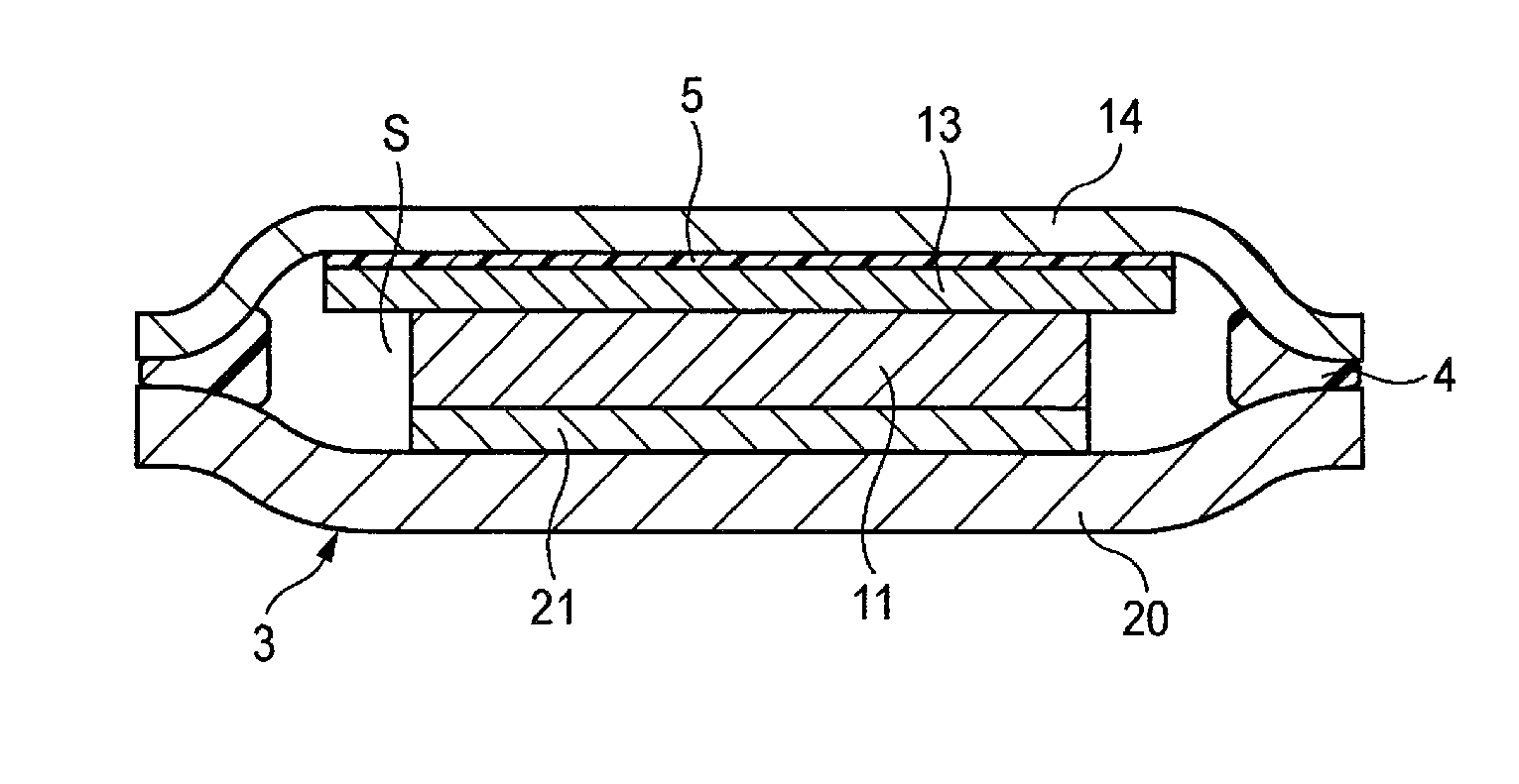
[0027]A radiological image detection apparatus 1 illustrated in FIG. 1 includes a radiological image conversion panel 2 and a sensor panel 3.

[0028]The radiological image conversion panel 2 includes a flexible support substrate 10 and a scintillator 11 which is formed of a phosphor for generating fluorescence upon exposure to radiation. The scintillator 11 is disposed on the support substrate 10.

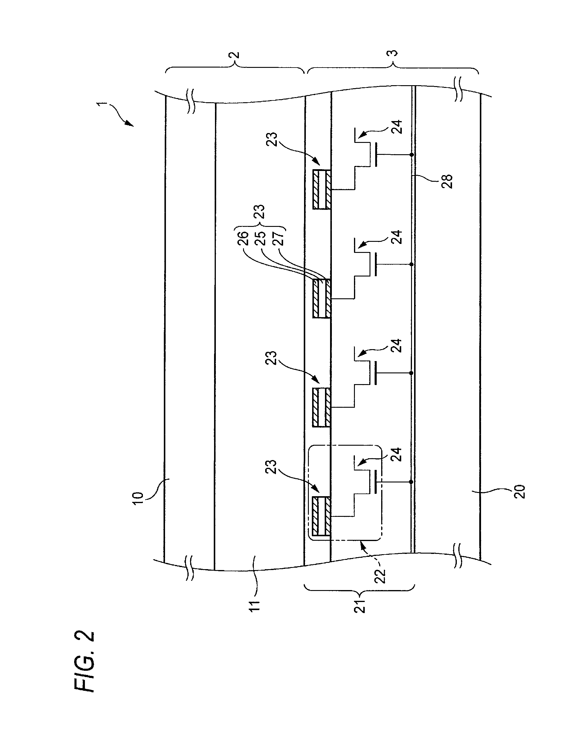
[0029]The sensor panel 3 includes a flexible insulating substrate 20 and a pixel array 21 disposed on the insulating substrate 20. Each of the pixels of the pixel array 21 detects the fluorescence generated from the scintillator 11.

[0030]The radiological image conversion panel 2 and the sensor panel 3 are arranged such that the scintillator 11 and the pixel array 21 are disposed facing to each other, and are bonded by a sealant 4.

[0031]The sealant ...


PUM

PropertyMeasurementUnit
apex angleaaaaaaaaaa
thicknessaaaaaaaaaa
diameteraaaaaaaaaa

Abstract

A radiological image detection apparatus includes a radiological image conversion panel and a sensor panel. A sealant that is disposed between a substrate of the radiological image conversion panel and a substrate of the sensor panel and surrounds a scintillator in the radiological image conversion panel and a pixel array in the sensor panel to form an isolated space on the inside of the sealant. The scintillator includes a columnar portion including a group of columnar crystals formed by growing crystals of the phosphor in columnar shapes and a surface configured by a set of tips of the columnar crystals is disposed in close contact with the pixel array without being bonded to the pixel array. Both of the substrate of the radiological image conversion panel and the substrate of the sensor panel are flexible, and the isolated space is depressurized.

Description

CROSS-REFERENCE TO RELATED APPLICATION[0001]This application claims the benefit of Japanese Patent Application No. 2011-188048, filed on Aug. 30, 2011, the entire contents of which are hereby incorporated by reference.BACKGROUND OF THE INVENTION[0002]1. Technical Field[0003]The present invention relates to a radiological image detection apparatus.[0004]2. Background Art[0005]Recently, a radiological image detection apparatus that utilizes a flat panel detector (FPD) for detecting a radiological image to generate digital image data has been put into practical use. The radiological image detection apparatus has been rapidly distributed because an image can be instantly confirmed as compared with an imaging plate configured by a photostimulable phosphor (accumulative phosphor). Various types of radiological image detection apparatus are available, one of which is known as an indirect conversion type.[0006]The indirect conversion type radiological image detection apparatus includes a sc...

Claims


Application Information

Patent Timeline
Patent Type & Authority Patents(United States)
IPC IPC(8): G01T1/20H01L27/146
CPCG01T1/2018H01L27/14618H01L27/14663H01L2924/0002Y10T156/10H01L2924/00G01T1/20187G01T1/20189
Inventor NAKATSUGAWA, HARUYASU
Owner FUJIFILM CORP
Why Eureka
Try Eureka