Method of combining dispersed light sources for projection display

a technology of dispersed light and projection display, which is applied in the direction of non-linear optics, lighting and heating apparatus, instruments, etc., can solve the problems of difficult routing of electrical power and control (data) connections, limited size, and waste of light energy in display systems

Active Publication Date: 2009-05-26
TEXAS INSTR INC
View PDF9 Cites 83 Cited by
  • Summary
  • Abstract
  • Description
  • Claims
  • Application Information

AI Technical Summary

Benefits of technology

[0016]These and other problems are generally solved or circumvented, and technical advantages are generally achieved, by preferred embodiments of the present invention, which achieve an advantageous array of light sources such as LEDs without detracting unduly from overall system performance.
[0019]An advantage of a preferred embodiment of the present invention is that it improves efficiency by manipulating the light cones exiting the tapered array to maximize transmission through the fly-eye lenses.
[0020]A further advantage of a preferred embodiment of the present invention is that multiple light sources, such as LEDs, may be used without having to place them close together on a substrate, greatly simplifying power attachments, cooling, and placement.

Problems solved by technology

As should therefore be apparent from FIG. 4, LED array 41 may be limited in size because a substantial portion of the light emitted from it must be received by convex lens 42, wasted light energy being undesirable in display systems.
Although this arrangement may produce satisfactory illumination for transmitting along optical path 40 (shown in FIG. 4), the close proximity of LEDs 51 through 56 means that the electrical power and control (data) connections may be difficult to route.
Moreover, the heat load building up on substrate 50 may be difficult to dissipate adequately.
And while an LED fixed array is in some ways more efficient, however, a small amount of overlap occurs in the distribution of emitted light spectrum between, for example, the green and blue LEDs.
But this rejection of light by the optics is not as pronounced as in a color wheel based projector using an arc lamp.
LED technology, however, has lagged behind arc lamp technology in being able to achieve comparable screen lumens.
LED arrays can be used in a projector but not enough LEDs can fit into the limited etendue (light collection capacity) of the DMD so that acceptable screen lumens can be achieved in the marketplace.
Power to each LED in any array can be increased but limitations are reached in allowable LED junction temperatures.
In other words, the buildup of heat may become a problem and limit the number of LEDs that can be used in the light source array or arrays.

Method used


Image

  • Method of combining dispersed light sources for projection display
  • Method of combining dispersed light sources for projection display
  • Method of combining dispersed light sources for projection display

Examples


Embodiment Construction

[0035]The making and using of the presently preferred embodiments are discussed in detail below. It should be appreciated, however, that the present invention provides many applicable inventive concepts that can be embodied in a wide variety of specific contexts. The specific embodiments discussed are merely illustrative of specific ways to make and use the invention, and do not limit the scope of the invention.

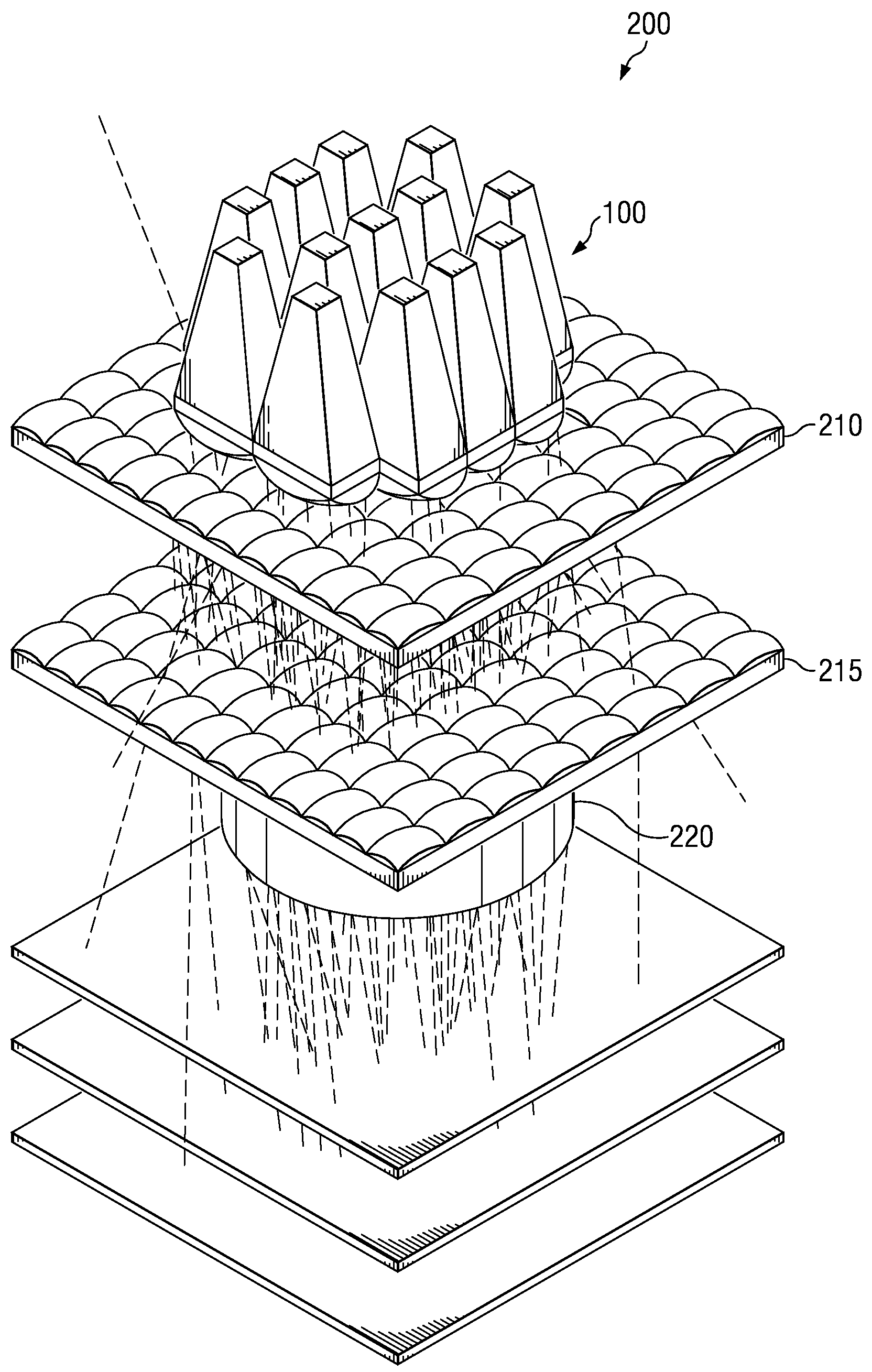
[0036]The present invention is directed to a method and system advantageously employed for optically combining the light emitted by dispersed light sources, such as multiple LEDs, used in a projection display system. The display system may, for example, produce visual images for a television or high-definition television (HDTV). While preferred embodiments of the present invention will herein be described with respect to such an application, other applications are possible. Any reference to a specific application such an HDTV is therefore intended to be exemplary and not limi...


PUM


Abstract

A method and system for combining light emitted by dispersed light sources for use in a projection display or similar system. A plurality of elongated and tapered light integrators are placed side by side forming an array, each having at their small input end a light source, such as an LED. Light collimated by each light integrator is further collimated by a convex lens disposed immediately at the output end of the light integrator. From the convex lenses, the light falls upon an array integrator, preferably a fly-eye type integrator, and passes through it to a second array integrator. Light emerging from the second array integrator is then passed through one or more relay lenses and falls upon a light modulator, such as a digital mircomirror device (DMD). The modulated light beam then passes through a projection lens and onto a visual image display screen. The display screen may, for example, be the screen of a high definition television (HDTV).

Description

TECHNICAL FIELD[0001]The present invention relates generally to optical display systems, and more particularly to a method and system for combining the light emitted by advantageously dispersed light sources, such as LEDs, for use in projection display systems.BACKGROUND[0002]Spatial light modulation (SLM) display systems are visual display systems that are used as an alternative to conventional cathode-ray tube (CRT) systems. SLM systems are used in a variety of applications such as television screens. One type of SLM may be referred to as a projection display system. Due to their superior clarity and performance, they are often used in high-end applications such as high-definition television (HDTV). Projection display systems transmit light produced by one or more light sources to create the display on a display screen. One popular projection display system is commercially available as DLP® (or Digital Light Processing®). DLP® utilizes a digital micromirror device (DMD), an array ...

Claims


Application Information

Patent Timeline
Patent Type & Authority Patents(United States)
IPC IPC(8): G03B21/14
CPCG02B26/0833G02B27/0961H04N9/3111H04N9/3152H04N9/3197G03B21/16G03B21/208G02B3/0056G02B3/0062
Inventor DEWALD, DUANE SCOTT
Owner TEXAS INSTR INC
Why Eureka
Try Eureka