Timepiece having mainspring winding state display apparatus including deformed segment gear
a technology of segment gear and display apparatus, which is applied in the direction of mechanical time indication, instruments, and horology, can solve the problems of retarded operation of winding mark hand (power reserve indicator), and achieve the effect of reducing the influence of mesh backlash and preventing operation
- Summary
- Abstract
- Description
- Claims
- Application Information
AI Technical Summary
Benefits of technology
Problems solved by technology
Method used
Image
Examples
first embodiment
(1) First Embodiment
(1•1) Total Constitution of Movement
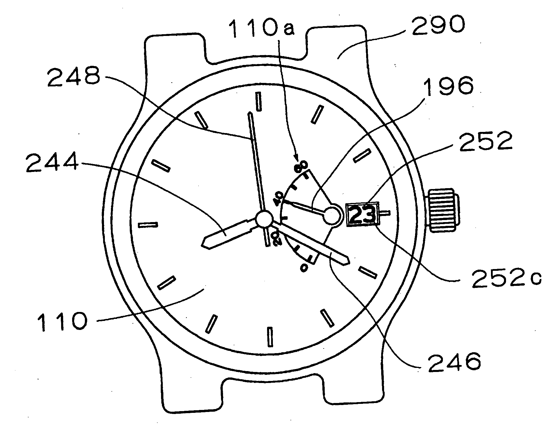
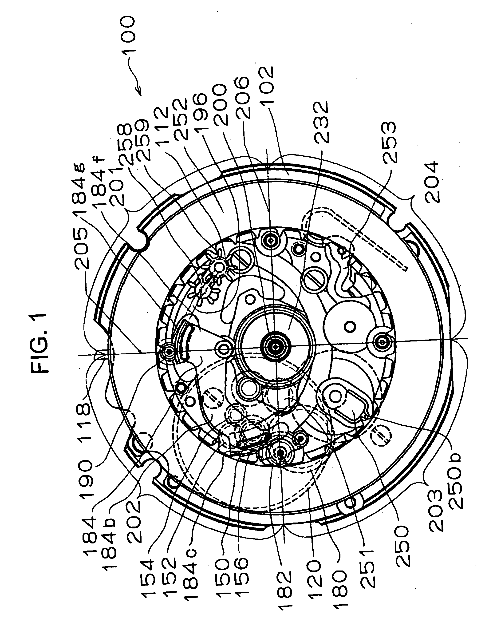
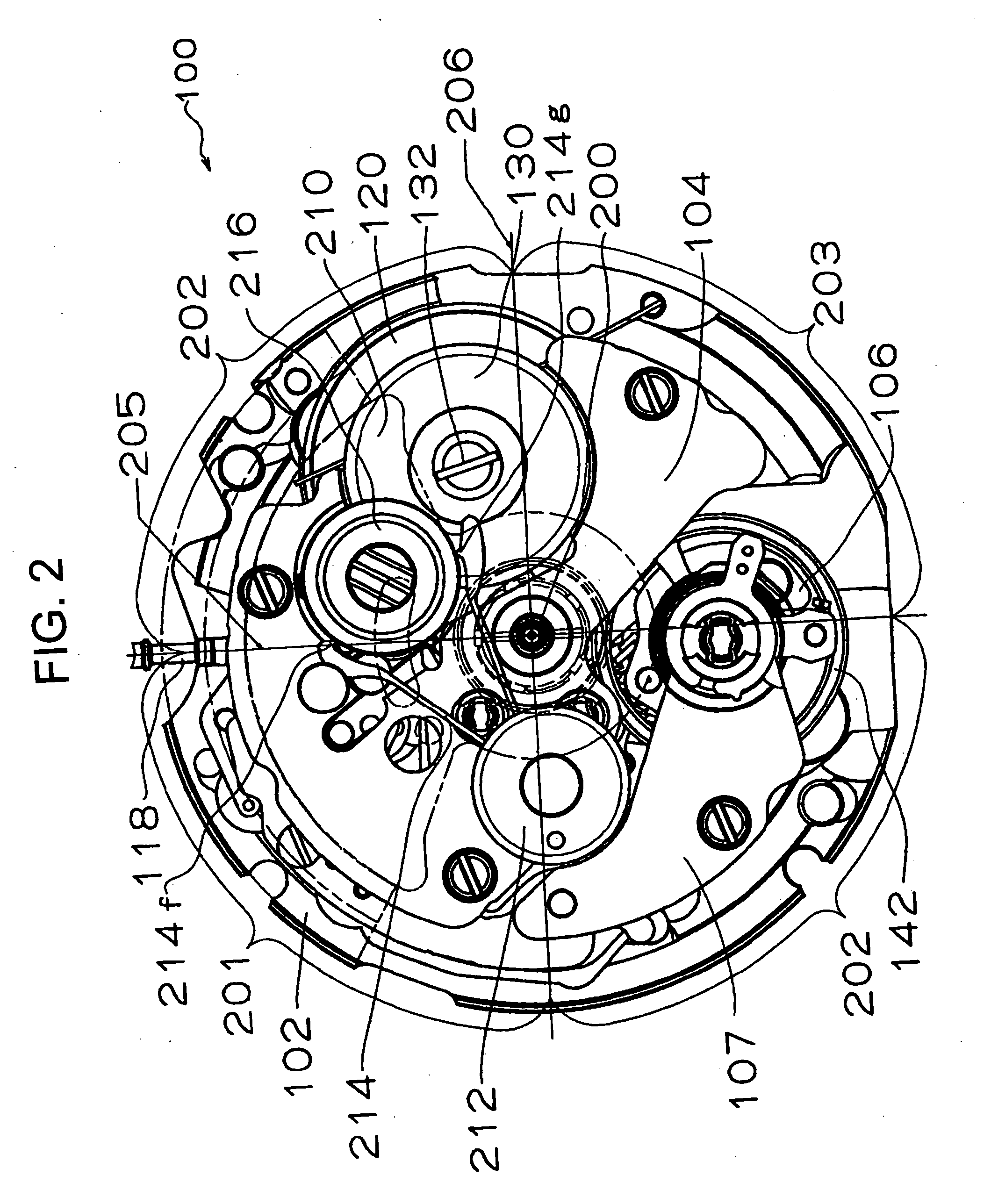
[0040] First, an explanation will be given of a first embodiment of a timepiece having a mainspring winding state display apparatus according to the invention. In reference to FIG. 1 through FIG. 4, a timepiece having a mainspring winding state display apparatus of the invention is provided with a movement 100. “Movement” indicates a machine body of the timepiece including a drive portion. Further, “complete” indicates a finished body of a timepiece in which a dial, indicators (hour hand, minute hand, second hand and the like), a crown and the like are attached to the movement of the timepiece to be contained in a time case (timepiece exterior). The movement 100 includes a main plate 102, a second main plate 112, and a date indicator maintaining plate 116. In the movement 100, “top side” indicates a side of two faces of the main plate 102 remote from glass of the timepiece case, that is, “case back side”. In the movement 100,...
second embodiment
(2) Second Embodiment
[0060] Next, a second embodiment of a timepiece having a mainspring winding state display apparatus of the invention will be explained. In the following explanation, a description will mainly be given of points of the second embodiment of the timepiece having the mainspring winding state display apparatus of the invention different from the first embodiment of the timepiece having the mainspring winding state display apparatus of the invention. Therefore, the above-described explanation of the first embodiment of the timepiece having the mainspring winding state display apparatus will be applied to a portion which is not described in the following. In reference to FIG. 6 through FIG. 8, according to the second embodiment of the timepiece having the mainspring winding state display apparatus of the invention, in a movement 320 of the timepiece having the mainspring winding state display apparatus, the rotational center of the winding mark display wheel 190 is arr...
third embodiment
(3) Third Embodiment
[0063] Next, a third embodiment of a timepiece having a mainspring winding state display apparatus of the invention will be explained. In the following explanation, a description will mainly be given of points of the third embodiment of the timepiece having the mainspring winding state display apparatus of the invention different from the first embodiment of the timepiece having the mainspring winding state display apparatus of the invention. Therefore, the above-described explanation of the first embodiment of the timepiece having the mainspring winding state display apparatus of the invention will be applied to a portion which is not described in the following. In reference to FIG. 9 and FIG. 10, according to the third embodiment of the timepiece having the mainspring winding state display apparatus of the invention, in a movement 330 of the timepiece having the mainspring winding state display apparatus, the rotational center of the winding mark indicator 190 ...
PUM
 Abstract
Description
Claims
Application Information
 - R&D
- Intellectual Property
- Life Sciences
- Materials
- Tech Scout
- Unparalleled Data Quality
- Higher Quality Content
- 60% Fewer Hallucinations
Browse by: Latest US Patents, China's latest patents, Technical Efficacy Thesaurus, Application Domain, Technology Topic, Popular Technical Reports.
© 2025 PatSnap. All rights reserved.Legal|Privacy policy|Modern Slavery Act Transparency Statement|Sitemap|About US| Contact US: help@patsnap.com


