
Signal recording method & apparatus, signal recording / reproducing method & apparatus and signal recording medium

Inactive Publication Date: 2005-07-28
SONY CORP
View PDF9 Cites 48 Cited by
  • Summary
  • Abstract
  • Description
  • Claims
  • Application Information

AI Technical Summary

Benefits of technology

[0008] The present invention addresses the problems described above. It is thus an object of the present invention to provide a technology that makes a continuous playback operation possible by assuring that the amount of data stored in a read buffer memory is large enough for eliminating a playback time break through reduction of the number of seek operations.

Problems solved by technology

In the case of a recorded signal split into a large number of segments as shown in FIG. 21(2), however, it is quite within the bounds of possibility that the amount of data stored in advance in the read buffer memory during the time is not large enough to be used for filling up a time gap between two consecutive segments.
As a result, the eventual playback signal can not be generated continuously.

Method used


Image

  • Signal recording method & apparatus, signal recording / reproducing method & apparatus and signal recording medium
  • Signal recording method & apparatus, signal recording / reproducing method & apparatus and signal recording medium
  • Signal recording method & apparatus, signal recording / reproducing method & apparatus and signal recording medium

Examples


Embodiment Construction

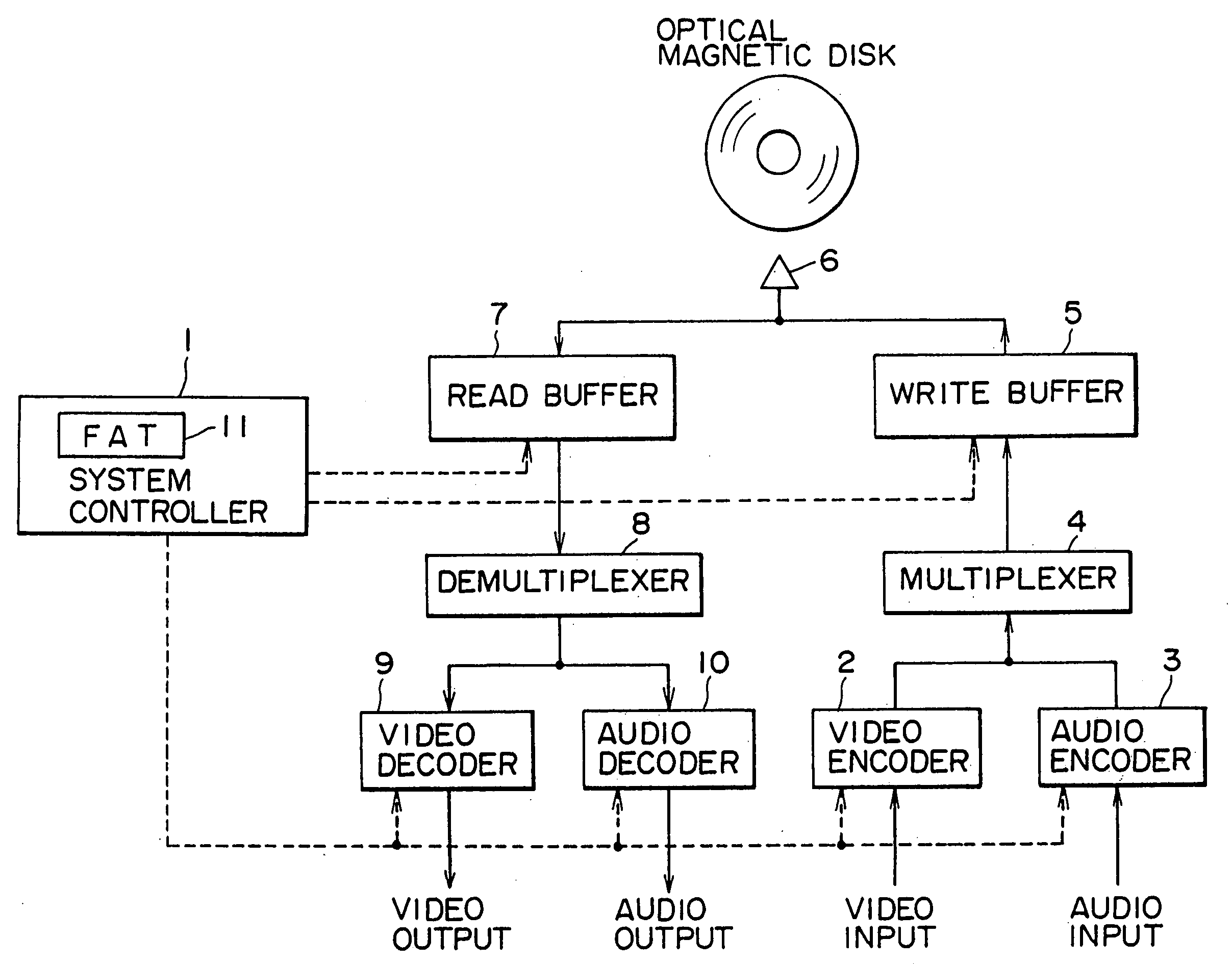
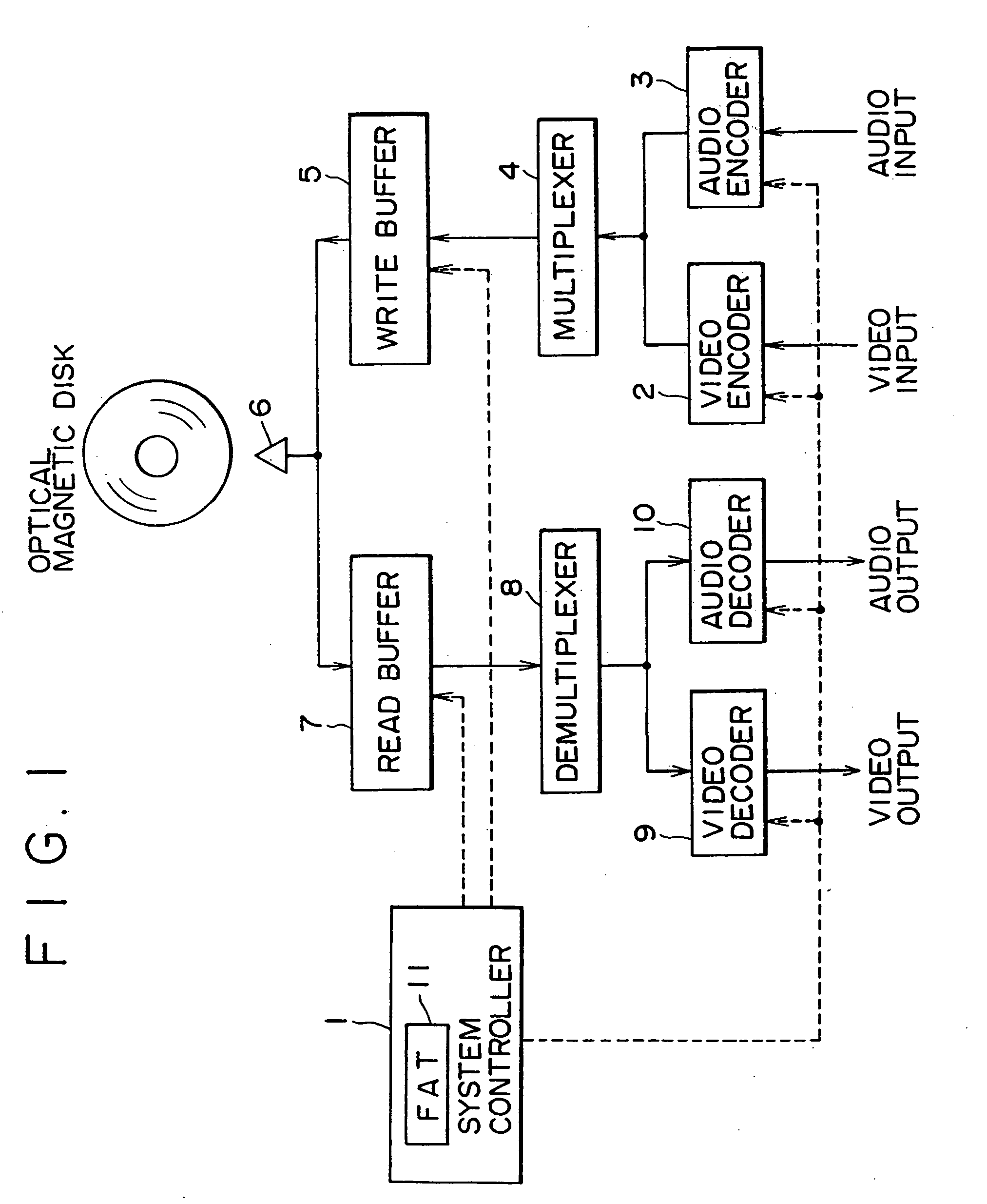
[0059] The above and other objects, features as well as many of the attendant advantages of the present invention will become more apparent and, thus, more readily appreciated as the same becomes better understood from a careful study of the following detailed description of a preferred embodiment of the present invention with reference to the accompanying diagrams. The description is divided into sections listed below which are explained sequentially in the order the sections are put on the following list: [0060] 1 Configuration of the Signal Recording / Playback Apparatus [0061] 2 Recording of an Additional Signal [0062] 3 Recognition of Free Areas [0063] 4 Editing [0064] 5 Optimization [0065] 6 Editing Details

1 Configuration of the Signal Recording / Playback Apparatus

[0066]FIG. 1 is a block diagram showing the configuration of a signal recording / playback apparatus to which the present invention is applied. The signal recording / playback apparatus records and plays back video and a...


PUM


Abstract

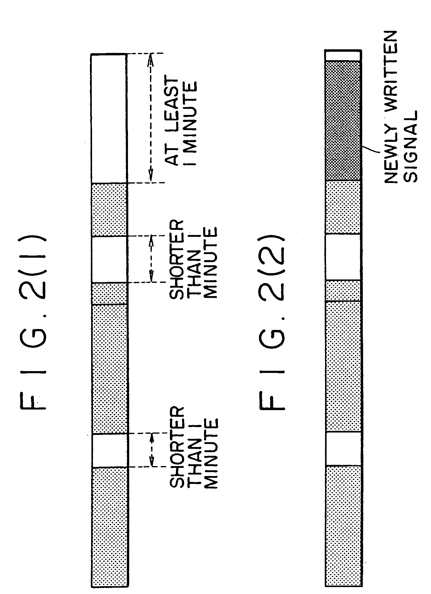
By reducing the number of seek operations in an operation to play back a signal from a recording medium, the amount of data temporarily stored in a read buffer memory employed in a signal recording / playback apparatus is large enough to be output as a playback signal during a seek operation, allowing a continuous playback operation to be carried out. In order to reduce the number of seek operations, a signal is always recorded onto the recording medium in continuous free areas each having a size equal to or larger than a predetermined recording / playback time length which is typically set at 1 minute. If it is necessary to insert an additional signal having a length smaller than the predetermined recording / playback time length into a point of insertion in an area already occupied by an existing signal, a continuous free area with a size equal to or larger than the predetermined recording / playback time length is newly allocated to the additional signal. The additional signal is then recorded in the free area instead of being inserted into the point of insertion. Since the free area is larger in size than the length of the additional signal, the rest of the free area is filled up with a portion of the existing signal adjacent to the point of insertion.

Description

BACKGROUND OF THE INVENTION [0001] The present invention relates to a technology for recording and playing back signals such as video and audio signals into and from an erasable recording medium such as an optical magnetic disc, a variable phase disc and a magnetic disc. [0002] By virtue of development of band compression technologies represented by the recently introduced MPEG (Moving Picture Experts Group) compression / coding technology, signals such as audio and video signals can now be recorded into a large capacity recording medium such as an optical magnetic disc for a playback operation of a long time. [0003] When a signal is recorded into such a recording medium, the signal undergoes a band compression / coding process, being recorded in sector units. The signal is then recorded into free areas on the recording medium. [0004] Traditionally, a signal continuous in the time axis direction resulting from typically editing work such as an audio or video signal is recorded into a re...

Claims


Application Information

Patent Timeline
IPC IPC(8): G11B20/10G11B27/00G11B27/032G11B27/034G11B27/036G11B27/10G11B27/11G11B27/32H04N5/783H04N9/804
CPCG11B20/10527H04N9/8045G11B27/034G11B27/036G11B27/105G11B27/11G11B27/329G11B2020/10592G11B2020/10916G11B2220/20G11B2220/216G11B2220/2525G11B2220/65G11B2220/90H04N5/783G11B27/032
Inventor TAKAHASHI, TAKAOOHTA, MASASHIAKIBA, TOSHIYATOMITA, MASAMISUITO, TARO
Owner SONY CORP
Learn More