Wavelength division multiplexed passive optical network

Inactive Publication Date: 2005-07-28
SAMSUNG ELECTRONICS CO LTD
View PDF2 Cites 11 Cited by
  • Summary
  • Abstract
  • Description
  • Claims
  • Application Information

AI Technical Summary

Benefits of technology

[0017] The present invention has been made to address the above-mentioned shortcomings of the related art. An object of the invention is to provide a WDM PON that can be inexpensively implemented while using a spectrum-sliced light source involving simple wavelength management, and without using expensive modulators.

Problems solved by technology

As a result, a heavy burden is imposed on subscribers.
The WDM PON is therefore not yet in widespread use.
However, the LiNbO3 modulators conventionally employed in the WDM PON are expensive.
Additionally, they exhibit a severe characteristic variation depending on the polarized state of the incoming light, and suffer high insertion loss.
The resulting overhead leads to additional expense and lost competitiveness.

Method used


Image

  • Wavelength division multiplexed passive optical network
  • Wavelength division multiplexed passive optical network
  • Wavelength division multiplexed passive optical network

Examples


first embodiment

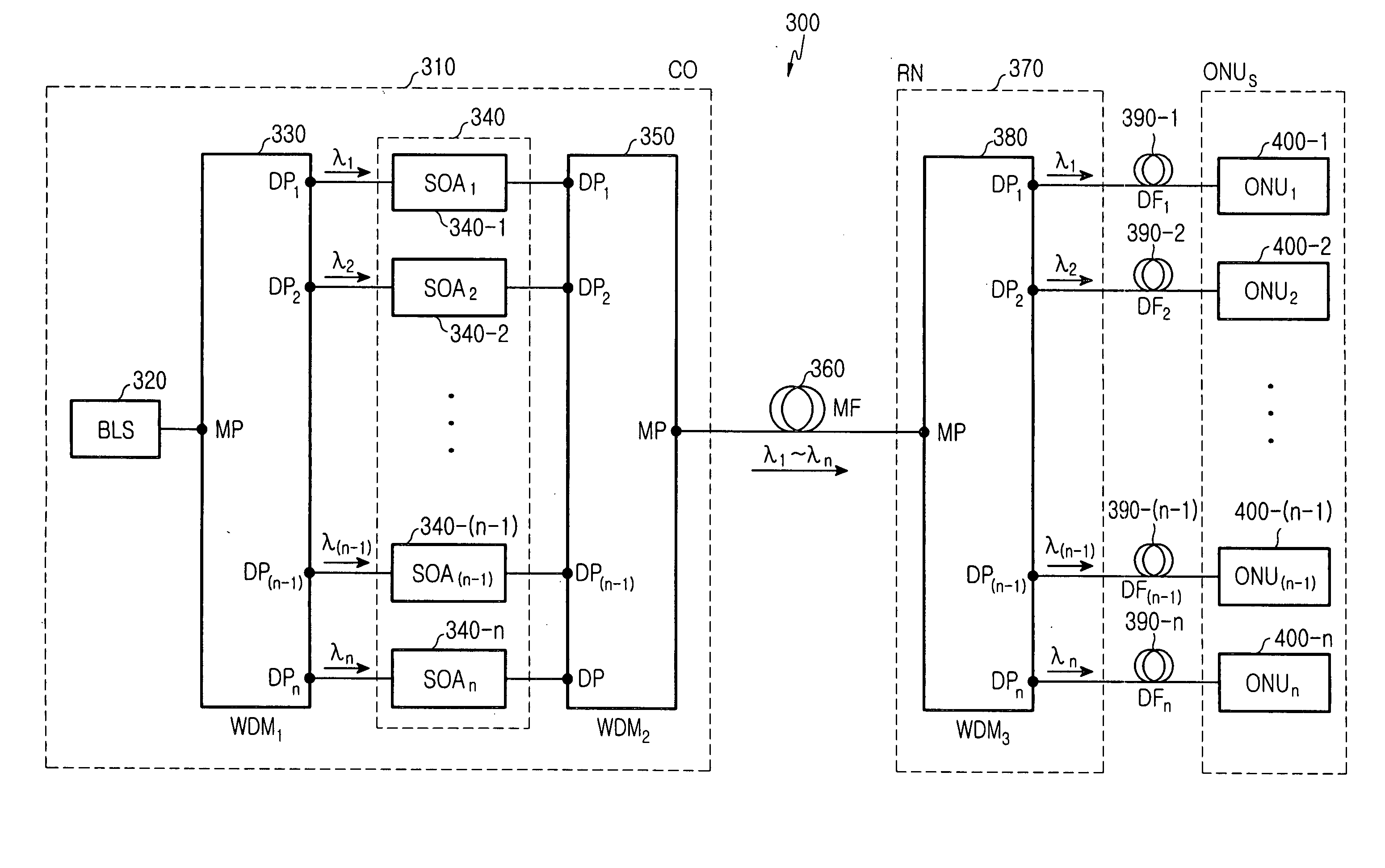
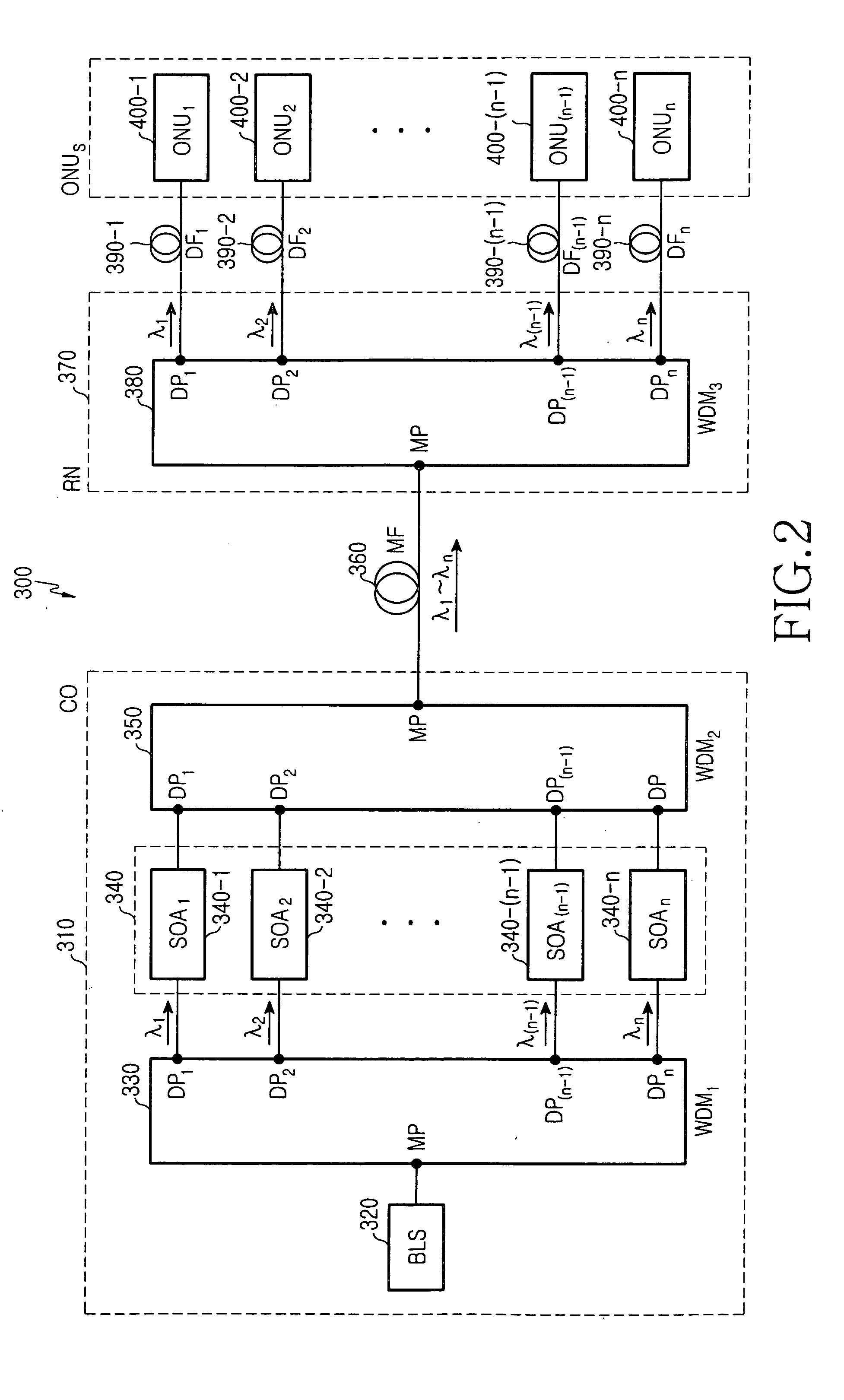
[0024]FIG. 2 illustrates a configuration of a WDM PON according to the present invention, which differs from the prior art embodiment of FIG. 1 in that the LiNbO3 modulators 140-1 to 140-n, and possibly additional loss-insertion-compensating amplifiers, are replaced with an array 340 of semiconductor optical amplifiers (SOAs) SOA1 340-1 to SOAn 340-n. The PON, which is designated by reference numeral 300 in FIG. 2, includes a central office (CO) 310, a remote node (RN) 370 connected to the central office 310 via a main optical fiber (MF) 360, and a plurality of optical network units (ONUs), ONU1 400-1 to ONUn 400-n, connected to the remote node 370 via a plurality of distribution optical fibers (DFs), DF1 390-1 to DFn 390-n, respectively.

[0025] The central office 110 includes a broadband light source 320, a first wavelength division multiplexer (WDM1) 330, n semiconductor optical amplifiers (SOAs), SOA1 340-1 to SOAn 340-n, and a second wavelength division multiplexer (WDM2) 350. Th...

second embodiment

[0032]FIG. 3 illustrates a configuration of a WDM PON according to the present invention. The PON 500 in FIG. 3 has a configuration similar to that of FIG. 2, except that it uses a variable optical attenuator (VOA) array 540 in place of the SOA array 340 used in the configuration of FIG. 2. The array 540 includes VOAs 540-1 to 540-n.

[0033] The PON 500 includes a central office (CO) 510 that incorporates the VOA array 540, and, as in the previous embodiment, the remote node (RN) 370, main optical fiber (MF) 360, the distribution optical fibers (DFs) 390-1 to 390-n and the plurality of optical network units (ONUs) 400-1 to 400-n.

[0034] Each of the VOA1 540-1 to VOAn 540-n generates a respective optical signal by using received external data to modulate light with an associated wavelength received from the WDM1530. The VOAs 540-1 to 540-n of the second embodiment of the present invention and the SOAs 340-1 to 340-n of the first embodiment of the present invention both variably adjust...


PUM


Abstract

A wavelength division multiplexed passive optical network (WDM PON) includes a central office that has: a broadband light source, a first wavelength division multiplexer to spectrum-slice light outputted from the light source, semiconductor optical amplifiers or variable optical attenuators, each modulating an associated one of spectrum-sliced lights in accordance with input data, and a second wavelength division multiplexer to multiplex optical signals respectively outputted from the semiconductor optical amplifiers. A remote node, connected to the central office via a main optical fiber, distributes the optical signals to distribution optical fibers, and, in, turn, to respective optical network units.

Description

CLAIM OF PRIORITY [0001] This application claims priority to an application entitled “WAVELENGTH DIVISION MULTIPLEXED PASSIVE OPTICAL NETWORK,” filed in the Korean Intellectual Property Office on Jan. 27, 2004 and assigned Serial No. 2004-4989, the contents of which are hereby incorporated by reference. BACKGROUND OF THE INVENTION [0002] 1. Field of the Invention [0003] The present invention relates to a passive optical network, and more particularly to a wavelength division multiplexed passive optical network using a spectrum-sliced light source. [0004] 2. Description of the Related Art [0005] A wavelength division multiplexed (WDM) passive optical network (PON) can provide ultrahigh-speed broadband communication services, using particular wavelengths assigned to respective subscribers. Accordingly, the WDM PON ensures communication security, and easily accommodates a separate communication service required by a subscriber, and expansion of communication capacity. To this latter po...

Claims


Application Information

Patent Timeline
IPC IPC(8): H04J14/02H04B10/12
CPCH04J14/02H04B10/2581H04B10/25
Inventor HWANG, SEONG-TAEKLEE, GYU-WOONGLEE, KWAN-SOOOH, YUN-JE
Owner SAMSUNG ELECTRONICS CO LTD
Why Eureka
Try Eureka