Terminal device of switching device

a switching device and terminal technology, applied in the direction of switching device connections, switch terminals/connections, relays, etc., can solve the problems of difficult to provide a sufficient space between the switching device and the connection module, difficult to hook a finger on the finger hook parts to lift the terminal lifters, etc., to improve the operability of wiring, improve the safety against electrical shock, and maintain the finger protection function.

Inactive Publication Date: 2005-07-28
FUJI ELECTRIC FA COMPONENTS & SYST CO LTD
View PDF6 Cites 7 Cited by
  • Summary
  • Abstract
  • Description
  • Claims
  • Application Information

AI Technical Summary

Benefits of technology

[0011] According to the present invention, the lifting arms of the terminal lifter may be provided with operation holes at upper ends thereof for inserting a screwdriver from side to lift the terminal lifter. When the terminal screw detached from the terminal strip is lifted and held on the case cover, a tool such as a screwdriver is inserted into the operation holes, or a finger is hooked on the operation holes, so that the terminal lifter is easily lifted.
[0012] According to the present invention, the lifting arms of the terminal lifter may be provided with finger hook grooves at upper ends thereof, so that the terminal lifter is easily lifted.
[0013] According to the present invention, the lifting arms of the terminal lifter may be provided with notches at bases thereof for dividing the support ring to bend easily. When the terminal lifter is fitted to the terminal screw, the support ring is easily widened, so that the terminal lifter is easily fitted to the head of the terminal screw.
[0014] According to the present invention, box-shaped terminal covers formed of upper and lower separable sections are attached to both end portions of a case of the switching device for covering the terminal boards. Accordingly, it is possible to obtain a protective structure with a finger protection level of IP20.
[0017] In the present invention, the terminal device is provided with the terminal lifter. Accordingly, as compared with a conventional terminal device in which a part (finger hook part) projects in a wiring direction from an end surface of a switching device case, the terminal lifter does not interfere with a wiring operation. Further, it is possible to access to the terminal lifter from the upper surface of the case cover of the switching device, thereby improving operability upon wiring as compared with the conventional terminal device.
[0018] In the invention, the box-shaped terminal cover is attached to the terminal device for covering the terminal boards. Accordingly, it is possible to obtain the protective structure with a finger protection level of IP20 (MEMA standard), thereby improving safety against an electrical shock. The terminal cover is divided into the upper cover and the lower cover. The lower cover engages the upper cover at a proper position in the vertical direction, so that the external wire insertion hole formed in the end surface of the cover can be widened or narrowed. Therefore, even if the size and number of external wires to be connected to the switching device are changed, it is possible to maintain the finger protecting function.

Problems solved by technology

Accordingly, when the switching case is installed in a switch board, a control board, or the like to connect external wires, or when a control module, an electromagnetic contactor, and the like located adjacent to the load side of the switching device are connected to each other via wires, the finger hook parts of the terminal lifters may interfere with the wires and make wiring difficult.
Also, when a connection module, an electromagnetic contactor, and the like are located close to the switching device, it is difficult to provide a sufficient space between the switching device and the connection module, the electromagnetic contactor, and the like.
Accordingly, it is difficult to hook a finger on the finger hook parts to lift the terminal lifters.

Method used


Image

  • Terminal device of switching device
  • Terminal device of switching device
  • Terminal device of switching device

Examples


Embodiment Construction

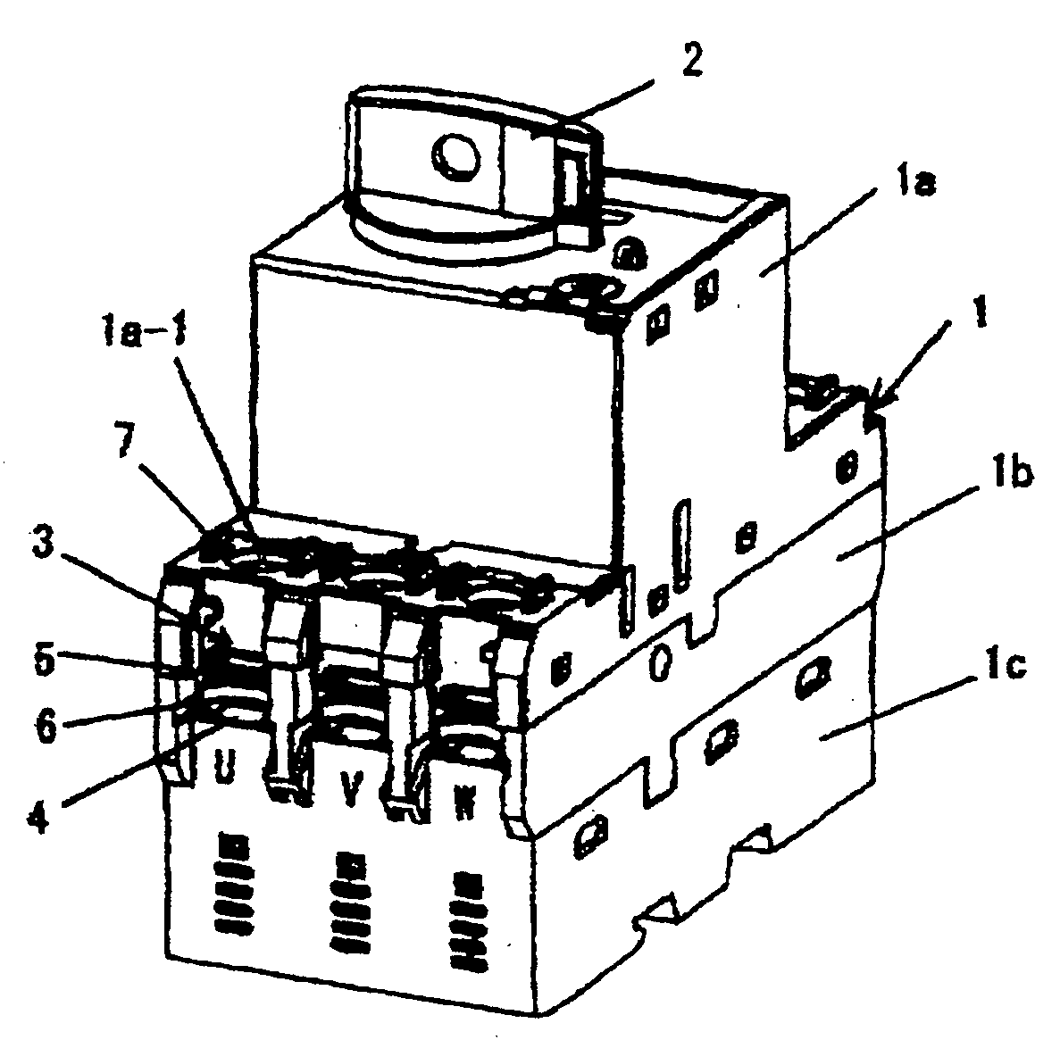
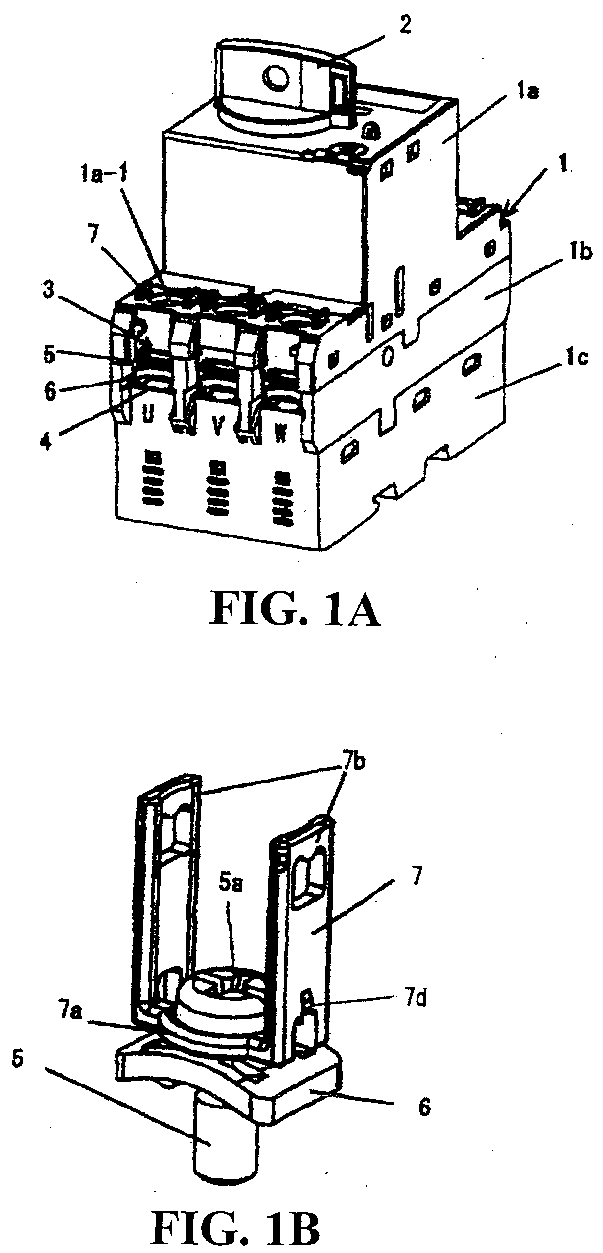
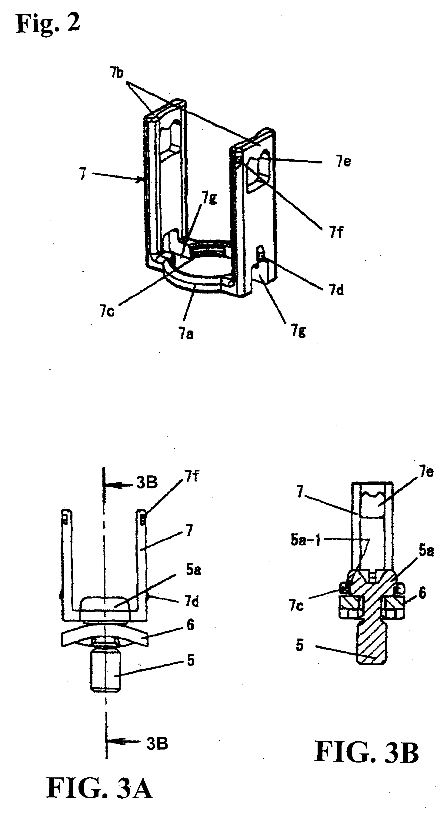
[0028] Hereunder, embodiments of the present invention will be described in detail with reference to the accompanying drawings. FIG. 1A is a view showing a switching device equipped with a terminal device according to the present invention (molded-case circuit breaker for a three-phase circuit), and FIG. 1B is a view showing a state that a washer and a terminal lifter are connected to a terminal screw.

[0029] In FIG. 1A, reference numeral 1 denotes a switching device case formed of a cover 1a, an intermediate case 1b, and a lower case 1c. Reference numeral 2 denotes a handle for a switching operation attached to an upper surface of the cover 1a. The switching device case 1 is provided with a power supply side terminal board and a load side terminal board at both ends thereof in a longitudinal direction. A terminal device 3 is arranged on the terminal board. The terminal device 3 is formed of main-circuit terminal strips 4 corresponding to U, V, and W phases drawn from a current brea...


PUM


Abstract

In a terminal device of a switching device, a terminal screw with a washer is screwed in a terminal strip having a screw hole therein for connecting an external wire. The terminal strips are placed on terminal boards of power supply side and load side formed at both ends of a switching device case. A case cover covers the terminal screw, and a screwdriver is inserted through an insertion hole formed in an upper surface of the case cover to tighten the terminal screw. The terminal device includes a terminal lifter connected to the terminal screw for manually lifting the terminal screw upwardly from the upper surface of the case cover, so that the terminal screw is temporally attached to the case cover at a lifted position after the terminal screw is loosened and detached from the terminal strip with the screwdriver.

Description

BACKGROUND OF THE INVENTION AND RELATED ART STATEMENT [0001] The invention relates to a terminal device of a switching device applied to a molded-case circuit breaker, an electromagnetic contactor, or the like for connecting external wires to main circuit terminals thereof. [0002] In a terminal device of a switching device, terminal screws combined with washers are screwed in terminal strips (terminal strips with screw holes) extending to power terminal boards of supply side and load side formed at both ends of a switching device case. Various press terminals (round or U-shape) of electric wires are inserted into the terminal boards from outside, and are fastened with the terminal screws to be connected to the terminal strips. The terminal device typically has a structure in which a case cover covers upper surfaces of the terminal boards having the terminal strips and the terminal screws except for external wire insertion sides to prevent an electric shock due to exposure. [0003] In...

Claims


Application Information

Patent Timeline
Patent Type & Authority Applications(United States)
IPC IPC(8): H01R4/38H01H1/58H01H9/02H01H50/02H01H50/14H01H71/08H01H73/20H01R4/30H01R4/34H01R9/00
CPCH01H1/5855H01H9/0264H01R4/34H01R4/305H01H71/08
Inventor KAWATA, HISAOKUBOYAMA, KATSUNORITAKEUCHI, SHINOBU
Owner FUJI ELECTRIC FA COMPONENTS & SYST CO LTD
Why Eureka
Try Eureka