Self-propelled vacuum cleaner

a self-propelled, vacuum cleaner technology, applied in carpet cleaners, carpet sweepers, electric equipment installation, etc., can solve the problems of cleaners that cannot prevent the rear portions of the side brushes from contacting with the floor, and the outer end portions of the side brushes cannot prevent dust scattering at the rear portions of the side brushes. achieve the effect of improving dust collection power

Inactive Publication Date: 2005-08-04
FUNAI ELECTRIC CO LTD
View PDF5 Cites 64 Cited by
  • Summary
  • Abstract
  • Description
  • Claims
  • Application Information

AI Technical Summary

Benefits of technology

[0008] An object of the present invention is to provide a self-propelled vacuum cleaner that can prevent dust gathered up by the front portion of a side brush from being scattered to the outside of the cleaner body by the rear portion of the side brush, thereby having improved dust collecting power.

Problems solved by technology

However, in such a conventional self-propelled vacuum cleaner, since the rotary shafts of the side brushes are arranged to extend in the vertical direction, the entire surfaces of the side brushes that face a floor come in contact with the floor.
However, the self-propelled vacuum cleaner as disclosed in the Japanese laid-open patent publication HEI 5-228090 has the following problem.
The cleaner can keep part of the surfaces of the side brushes that face a floor from contacting the floor due to the rotary shafts arranged in the cleaner body to be angled with respect to the vertical direction, but since the rotary shafts are biased so that the outer ends of the side brushes come in contact with a floor, the cleaner cannot prevent the outer end portions of the side brushes at the rear portions from contacting with a floor.
Accordingly, the cleaner cannot sufficiently prevent dust scattering at the rear portions of the side brushes.

Method used


Image

  • Self-propelled vacuum cleaner
  • Self-propelled vacuum cleaner
  • Self-propelled vacuum cleaner

Examples


Embodiment Construction

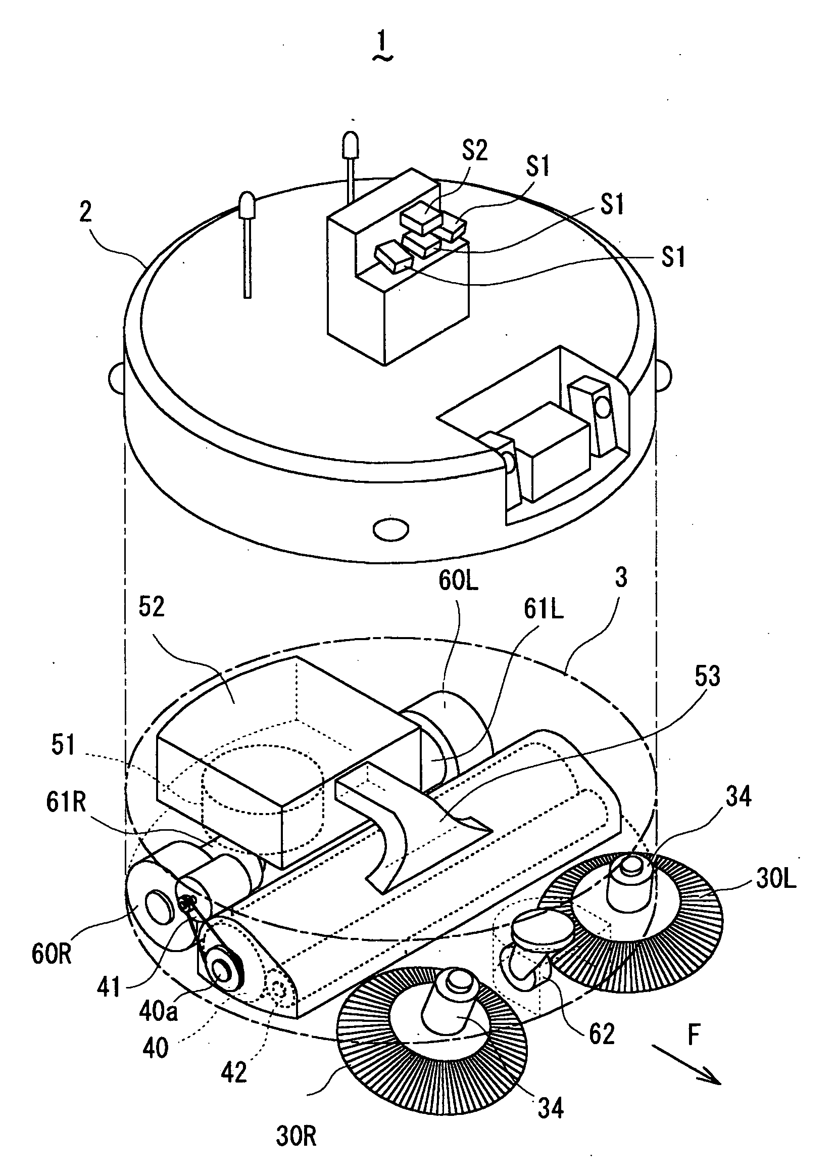
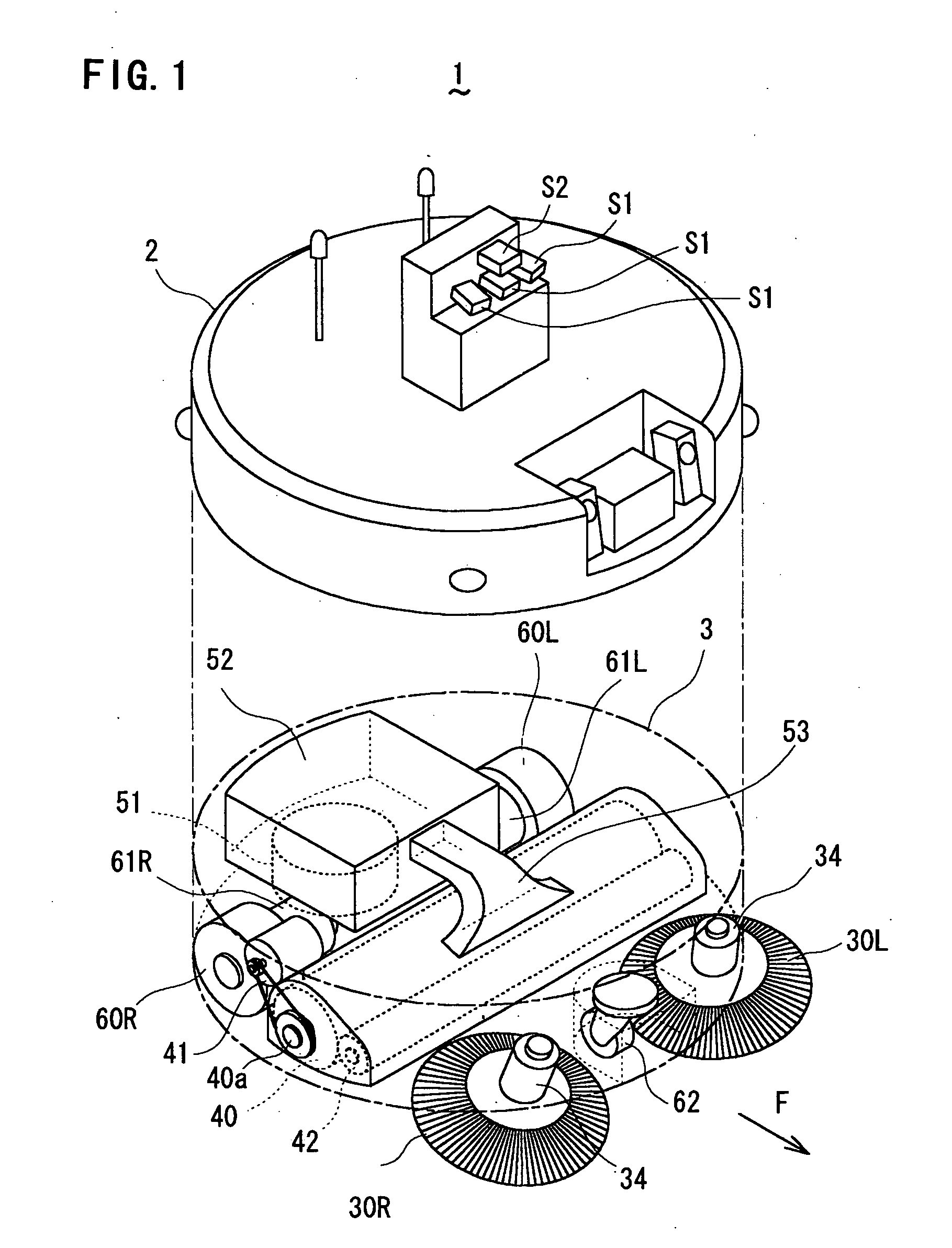
[0021] Referring now to the accompanying drawings, a self-propelled vacuum cleaner embodying the present invention will be described. FIG. 1 shows a cleaner body 1 of the self-propelled vacuum cleaner according to this embodiment, which is a device that autonomously moves on a floor surface to clean the floor surface. The cleaner body 1 comprises: a behavior control unit 2 that determines an area to be cleaned based on output signals of a plurality of sensors S1, S2, etc. and controls a cleaning operation of the cleaner body 1; and a dust collection unit 3 that moves around a floor surface based on control signals from the behavior control unit 2 to remove dust from the floor. In FIG. 1, the cleaner body 1 comprising the behavior control unit 2 and the dust collection unit 3 is separated into the behavior control unit 2 and the dust collection unit 3 for purposes of illustration.

[0022] The dust collection unit 3 comprises a pair of side brushes 30R and 30L provided at right and lef...


PUM


Abstract

A self-propelled vacuum cleaner having right and left side brushes for directing dust on a floor surface toward the inside of the bottom of the cleaner body. The right side brush rotates in a counterclockwise direction as viewed from top on a rotary shaft, which is tilted so that the lower end is located toward the right of and the rear of the cleaner body as compared with the upper end. The left side brush rotates in a clockwise direction as viewed from top on a rotary shaft, which is tilted so that the lower end is located toward the left of and the rear of the cleaner body as compared with the upper end. The tilted rotary shafts can prevent the outer portions of the side brushes at their rear portions from contacting a floor surface, thereby preventing dust collected by the front portions of the side brushes from being scattered to the outside of the cleaner body by the rear portions of the brushes.

Description

BACKGROUND OF THE INVENTION [0001] 1. Field of the Invention [0002] The present invention relates to a self-propelled vacuum cleaner, and more particularly to a self-propelled vacuum cleaner having side brushes for directing dust on a floor surface toward the inside of the cleaner body. [0003] 2. Description of the Related Art [0004] Self-propelled vacuum cleaners are known that have drive motors mounted in the main body thereof for driving wheels so as to clean a surface while controlling movement of the main body by controlling the drive motors. Especially in recent years, self-propelled vacuum cleaners capable of autonomous movement have been developed that can clean a surface while autonomously determining an area to be cleaned based on output signals of a plurality of sensors. [0005] Some of the conventional self-propelled vacuum cleaners have side brushes. The side brushes are mounted at both sides of a cleaner body, and rotate on rotary shafts extending in the vertical direct...

Claims


Application Information

Patent Timeline
Patent Type & Authority Applications(United States)
IPC IPC(8): A47L5/00A47L5/30A47L9/00A47L9/28A47L11/24A47L11/283A47L11/32E01H1/08
CPCA47L5/30A47L11/32A47L11/4002A47L11/4011A47L2201/00A47L11/4038A47L11/4041A47L11/4069A47L11/4013
Inventor UEHIGASHI, NAOYA
Owner FUNAI ELECTRIC CO LTD
Why Eureka
Try Eureka