Gas turbine cooling system

a technology of cooling system and gas turbine engine, which is applied in the direction of machines/engines, turbine/propulsion fuel heating, lighting and heating apparatus, etc., can solve the problems of degradation of fuel delivery performance, and limited so as to and increase the usable cooling capacity of fuel

Active Publication Date: 2005-08-04
RTX CORP
View PDF16 Cites 6 Cited by
  • Summary
  • Abstract
  • Description
  • Claims
  • Application Information

AI Technical Summary

Benefits of technology

[0005] This invention is an engine cooling system including a fuel deoxygenator for removing dissolved oxygen from fuel to increase the usable cooling capacity of fuel used for cooling engine cooling air.
[0006] A gas turbine engine includes a compressor compressing air to a high pressure. The high-pressure air is mixed with fuel in a combustor and ignited to produce hot combustion gases. The hot combustion gases drive a turbine. The turbine is cooled by air bled off from the compressor. The cooling air from the compressor is cooled within a fuel / air heat exchanger. Removing substantially all the dissolved oxygen in the fuel deoxygenator increases the usable cooling capacity of the fuel by increasing the temperature at which coke deposits are formed.
[0007] The increased cooling capacity of the fuel enables an increase in the amount of heat that can be absorbed from the cooling air, which in turn enables increased engine operating temperatures. As appreciated, higher engine temperatures result in greater engine efficiencies, that in turn result in favorable performance improvements.
[0008] Accordingly, the engine cooling system of this invention increases the usable cooling capacity of fuel used to cool engine cooling air.

Problems solved by technology

The usable cooling capacity of fuel is limited by coke formation caused by oxidative reactions with dissolved oxygen within the fuel.
Coke deposits can cause degradation of fuel delivery performance.
Therefore, the usable cooling capacity of the fuel is limited by the amount of dissolved oxygen within the fuel.
Further, the usable cooling capacity of the fuel limits the amount of heat that can be transferred from the engine cooling air, and that in turn limits sustainable engine operating temperatures.

Method used


Image

  • Gas turbine cooling system
  • Gas turbine cooling system
  • Gas turbine cooling system

Examples


Embodiment Construction

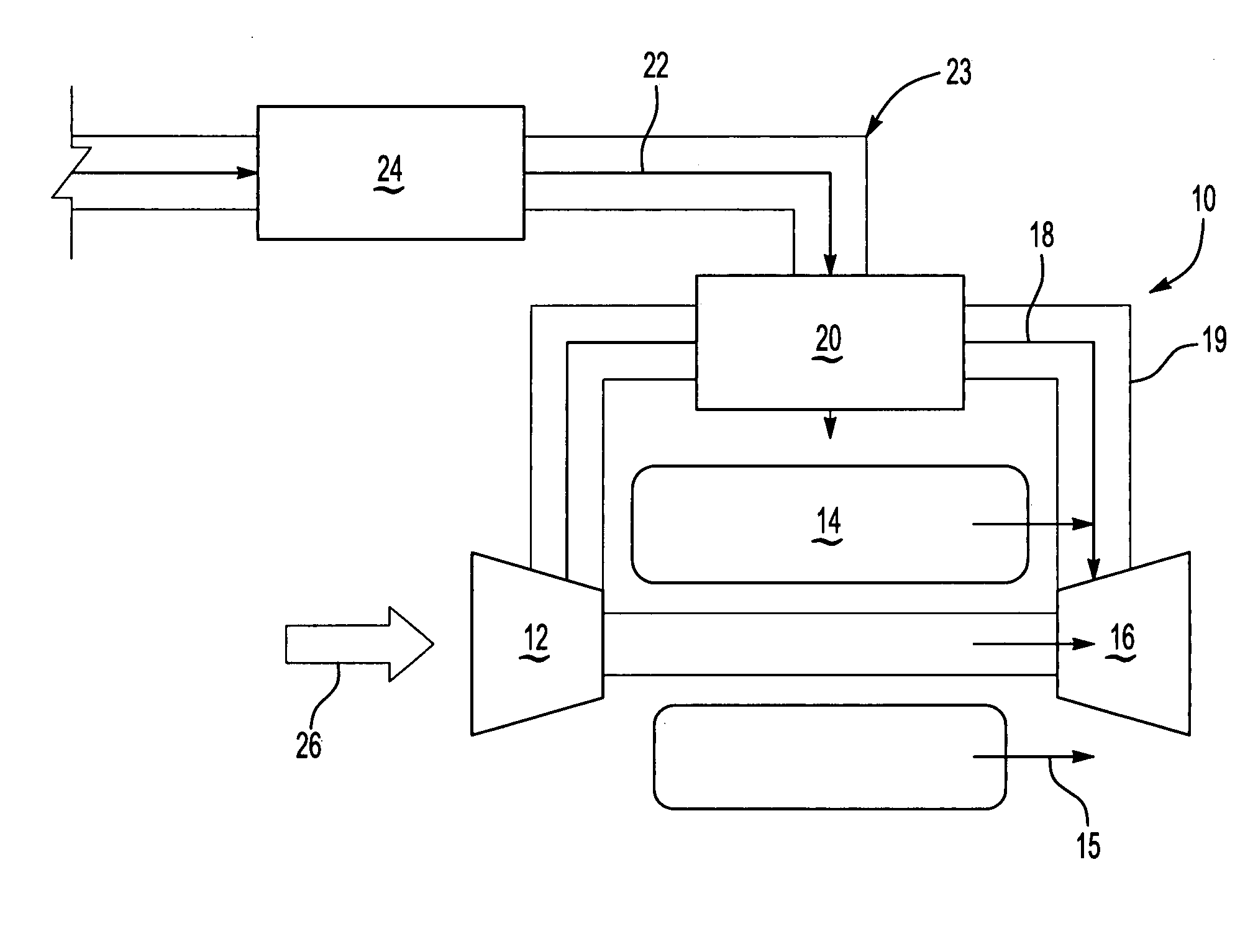
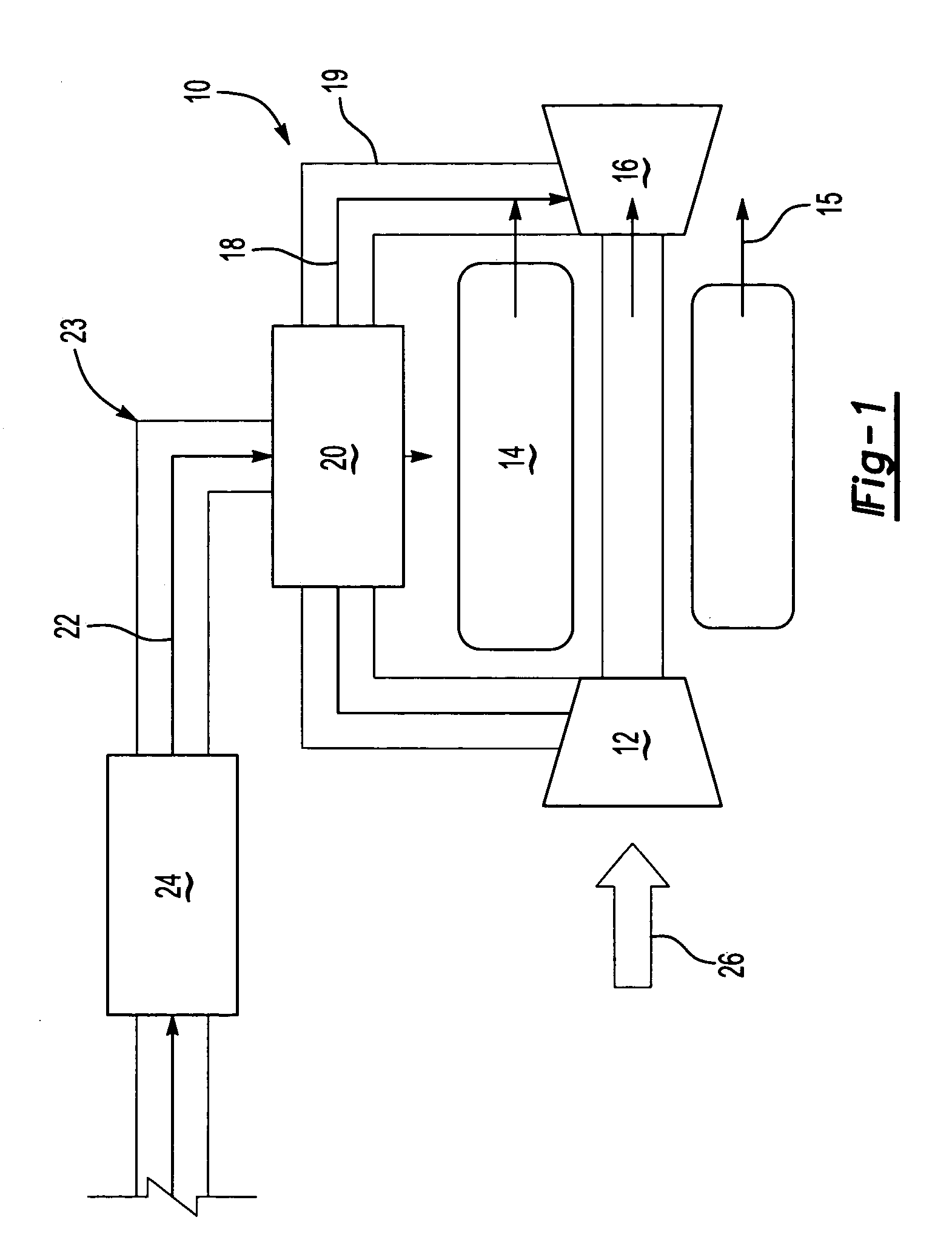
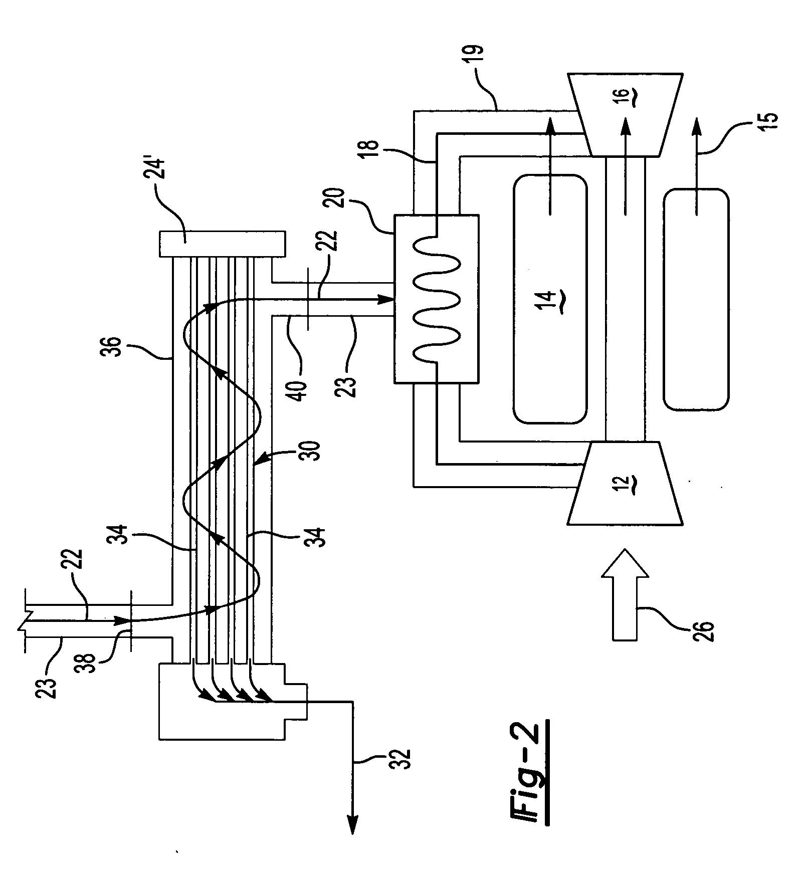
[0014] Referring to FIG. 1, a gas turbine engine assembly 10 includes a compressor 12 a combustor 14 and a turbine 16. Airflow 26 entering the compressor 12 is compressed to a high pressure and directed towards the combustor 14. In the combustor 14, fuel 22 is mixed with the high-pressure air and ignited. Resulting hot combustion gases 15 are exhausted to drive the turbine 16.

[0015] Hot combustion gases 15 exhausted to drive the turbine 16 are typically at temperatures that can potentially damage metal components of the engine 10. An air passage 19 leading from the compressor 12 supplies high-pressure air 18 to the turbine 16. High-pressure air 18 creates a boundary layer that insulates metal components from the hot combustion gases 15 flowing over the turbine 16.

[0016] The air 18 within the air passage 19 cooling the turbine 16 must be at a temperature that provides the desired cooling benefits to the turbine 16. The greater the temperature of the air flowing over the turbine 16,...


PUM


Abstract

A cooling system for a gas turbine engine includes a fuel deoxygenator for increasing the cooling capacity of the fuel. The fuel deoxygenator removes dissolved gases from the fuel to prevent the formation of insoluble deposits. The prevention of insoluble deposits increases the usable cooling capacity of the fuel. The increased cooling capacity of the deoxygenated fuel provides a greater heat sink for cooling air used to protect engine components. The improved cooling capacity of the cooling air provides for increased engine operating temperatures that improves overall engine efficiency.

Description

BACKGROUND OF THE INVENTION [0001] This invention generally relates to a cooling system for a gas turbine engine, and specifically to a cooling system including a fuel deoxygenator to increase the usable heat absorption capability of fuel used for cooling cooling air. [0002] A gas turbine engine typically includes a compressor, a combustor and a turbine. Air entering the compressor is compressed and directed toward the combustor. In the combustor, fuel is combined with the high-pressure air and ignited. Combustion gases produced in the combustor drive the turbine. High engine temperatures provide better fuel burn rates and engine efficiencies that extend the range of an aircraft. The high engine and combustion gas temperatures are greater than can normally be accommodated by metal parts of the engine. Typically, a portion of air from the compressor is bled off and directed over parts of the engine to form a cooling boundary layer that insulates exposed surfaces from the hot combusti...

Claims


Application Information

Patent Timeline
Patent Type & Authority Applications(United States)
IPC IPC(8): F02C3/24F02C7/12F02C7/18F02C7/22F02C7/224
CPCB01D19/0031F02C7/185Y02T50/675Y02T50/672F02C7/224F23K2900/05082Y02T50/60A01K91/04
Inventor SPADACCINI, LOUIS J.HUANG, HEBERTUCCIOLI, LUCABAYT, ROBERT L.
Owner RTX CORP
Why Eureka
Try Eureka