
Door closing apparatus

a technology for closing apparatus and doors, which is applied in the field of door closing apparatus, can solve the problems of uneven and the disassembly of the first actuation lever and the second actuation lever may not be smooth, and achieves smooth operation.

Active Publication Date: 2005-08-04
MITSUI KINZOKU ACT
View PDF8 Cites 38 Cited by
  • Summary
  • Abstract
  • Description
  • Claims
  • Application Information

AI Technical Summary

Benefits of technology

The present invention provides a door closing apparatus that is smooth in operation. The apparatus includes a latch mechanism, an actuator, a rotary body, a first actuation lever, a second actuation lever, and a cancel lever. The apparatus is designed to bring the half-closed state of the door to the fully-closed state. The cancel lever is designed to engage with the rotary body and cancel engagement when the operation handle on the door is operated for opening. The technical effect of this invention is to provide a door closing apparatus that allows for smooth operation and secure closing of doors.

Problems solved by technology

Therefore, it becomes difficult to cause the cancel lever to perform the door opening action to move the engaging pin smoothly in a sliding manner according to an opening operation of the inside handle or the outside handle conducted by a user.
Consequently, disabling of drive of the actuator may not be performed smoothly.
As a result, disabling of drive of the actuation may not be performed smoothly.
Particularly, in the door closing apparatus, since the first actuation lever moves straightly, a relatively large force against frictional resistance is required for causing the cancel lever to perform the door opening action between the first actuation lever moving straightly and the cancel lever, which results in difficulty in smooth disengagement between the first actuation lever and the second actuation lever.

Method used


Image

  • Door closing apparatus
  • Door closing apparatus
  • Door closing apparatus

Examples


Embodiment Construction

[0022] Exemplary embodiments of a door closing apparatus according to the present invention will be explained in detail with reference to the accompanying drawings. Note that the invention is not limited thereto.

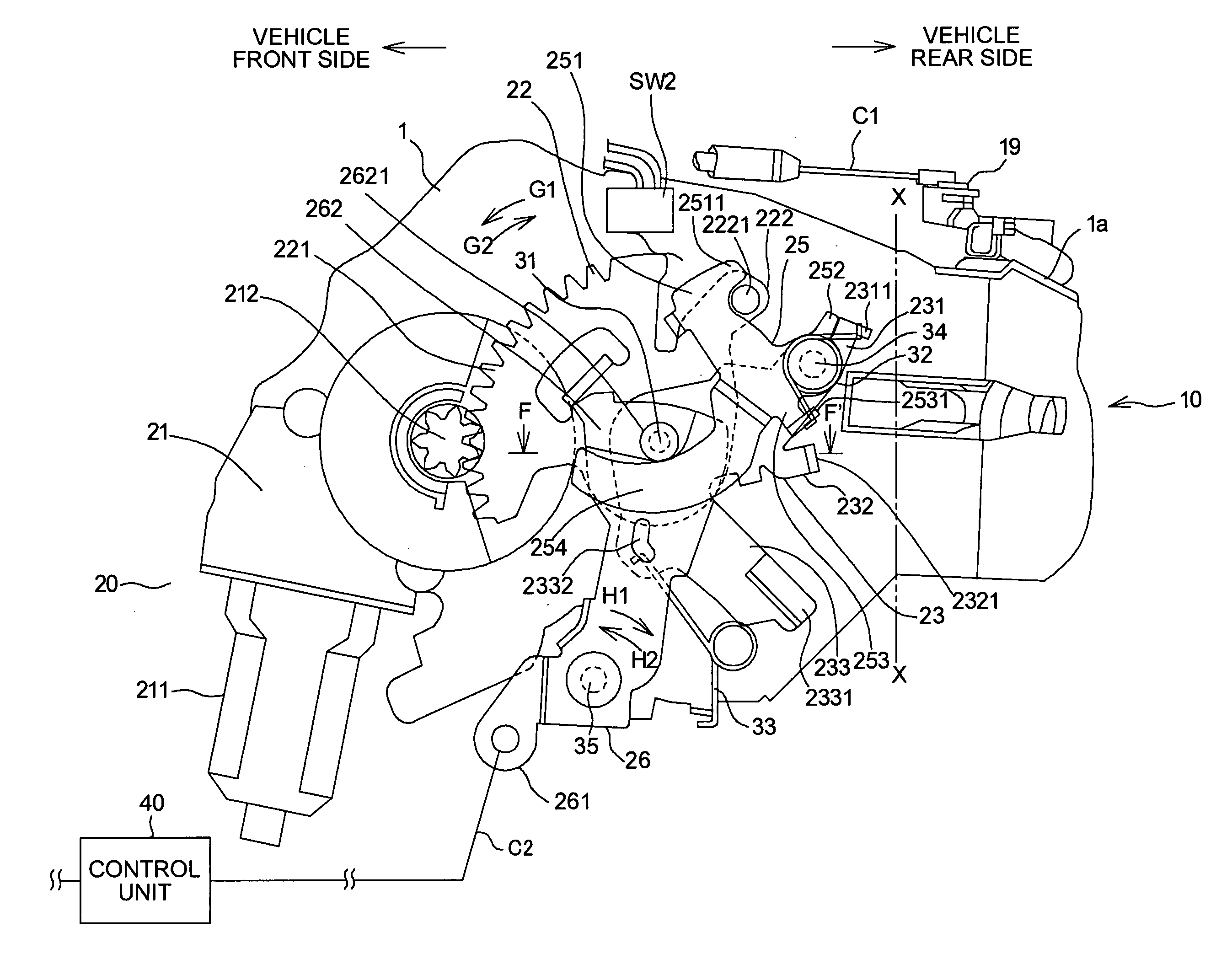
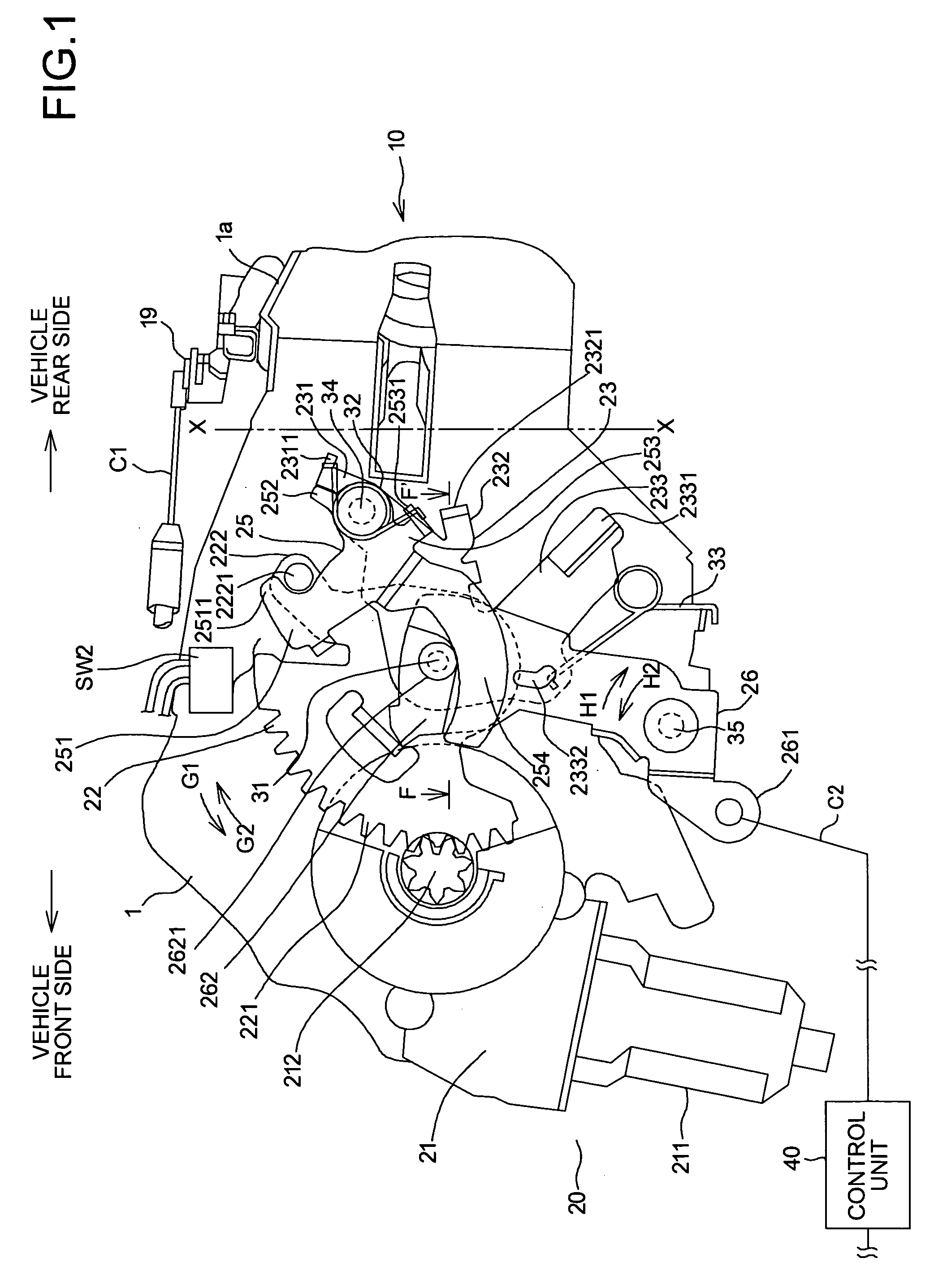
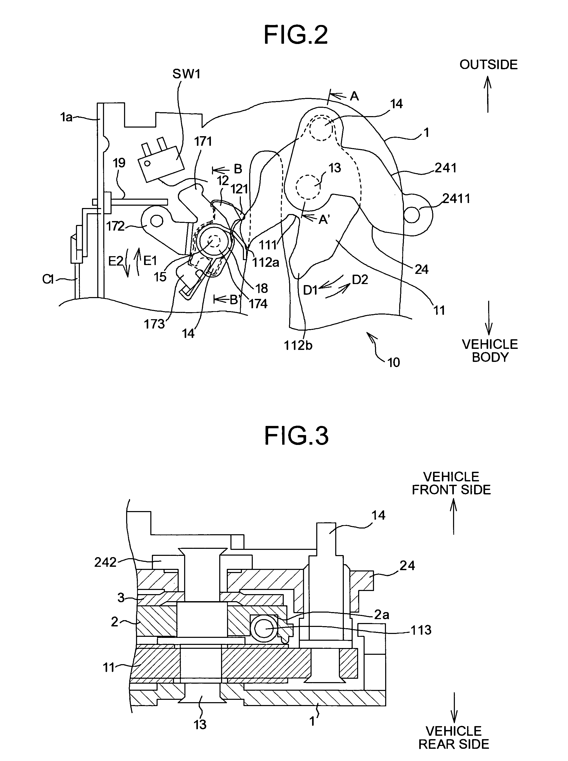
[0023] A door closing apparatus according to an embodiment of the present invention will be explained below in such a manner that the door closing apparatus is applied to a slide door arranged openably / closably to a vehicle body, for example, a four-wheel automobile. FIGS. 1 and 2 are diagrams of a main unit of the door closing apparatus according to an embodiment of the present invention. FIG. 1 is an explanatory diagram of the main unit, as viewed from an opposite side (an outer side) to the vehicle body, where a left side on the drawing denotes the vehicle front side, and a right side thereon denotes the vehicle rear side. FIG. 2 is an explanatory diagram of the door closing apparatus shown in FIG. 1, as viewed from the vehicle front side, where an upper side on the draw...


PUM


Abstract

A door closing apparatus has a latch mechanism that holds a door in a half-closed state and a fully-closed state to a vehicle body. An actuator drives the door when the door is in the half-closed state, a sector gear rotates as the actuator is driven. A first close lever performs closing action according to rotation of the sector gear, and a second close lever performs a door closing action according to the closing action to cause the latch mechanism to perform the closing action. A cancel lever is swingably disposed to the first close lever via a first spring. The cancel lever comes in engagement with the sector gear in a normal state, while performing a door opening action against the biasing force of the first spring to cancel the engagement with the sector gear when an opening operation of an operation handle is performed.

Description

BACKGROUND OF THE INVENTION [0001] 1) Field of the Invention [0002] The present invention relates to a door closing apparatus that is applied to vehicles. [0003] 2) Description of the Related Art [0004] Conventionally, in a vehicle, for example, a four-wheel automobile, when a door such as a slide door is in a half-closed state (a non-complete closed state) towards a vehicle body, a door closing apparatus for bringing the door to a fully-closed state (a completely-closed state) has been known. [0005] As one example of such the door closing apparatus, there is an apparatus provided with a latch mechanism that is arranged in the door to hold the door in a half-closed state and a fully-closed state to a vehicle body, and an actuator that is driven when the door is in the half-closed state. A first actuation lever (active lever) interlocked with the actuator performs a closing action according to drive of the actuator and a second actuation lever (passive lever) engaged with the first a...

Claims


Application Information

Patent Timeline
Patent Type & Authority Applications(United States)
IPC IPC(8): B60J5/00E05B83/36E05B79/08E05B81/20E05B83/40
CPCE05B81/21E05B81/20Y10T292/1082
Inventor YONEYAMA, FUMIHIRO
Owner MITSUI KINZOKU ACT
Learn More