System and method for packaging design

Inactive Publication Date: 2005-08-04
QUARK INC
View PDF2 Cites 7 Cited by
  • Summary
  • Abstract
  • Description
  • Claims
  • Application Information

AI Technical Summary

Benefits of technology

[0013] Views of the structure can be exported to allow collaborative editing of the structure. Multiple designers, managers and clients can electronically view and ver

Problems solved by technology

This process was cumbersome and time-consuming.
Numerous problems occur with this workflow process.
One such problem is need for several packages to provide the conversion, editing and output of the design drawings.
Another problem is the inability to accurately visualize the final appearance of the assemb

Method used


Image

  • System and method for packaging design
  • System and method for packaging design
  • System and method for packaging design

Examples


Embodiment Construction

[0027] The present invention provides systems and methods for designing packaging and graphics for packaging. It is to be expressly understood that the descriptive embodiments set forth herein are intended for explanatory purposes and is not intended to unduly limit the scope of the claimed inventions. Other embodiments and applications not described herein are considered to be within the scope of the claimed inventions.

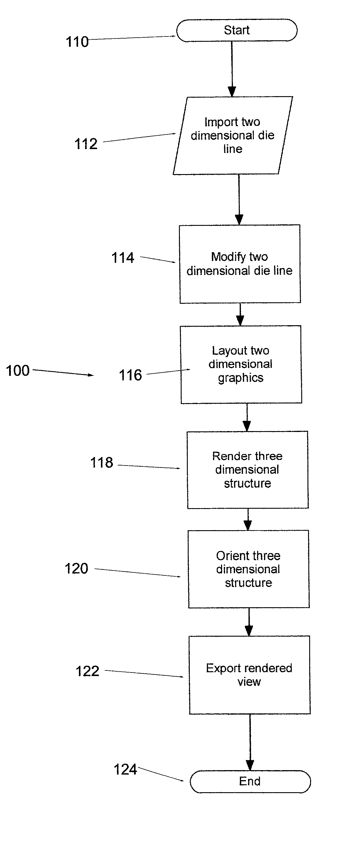
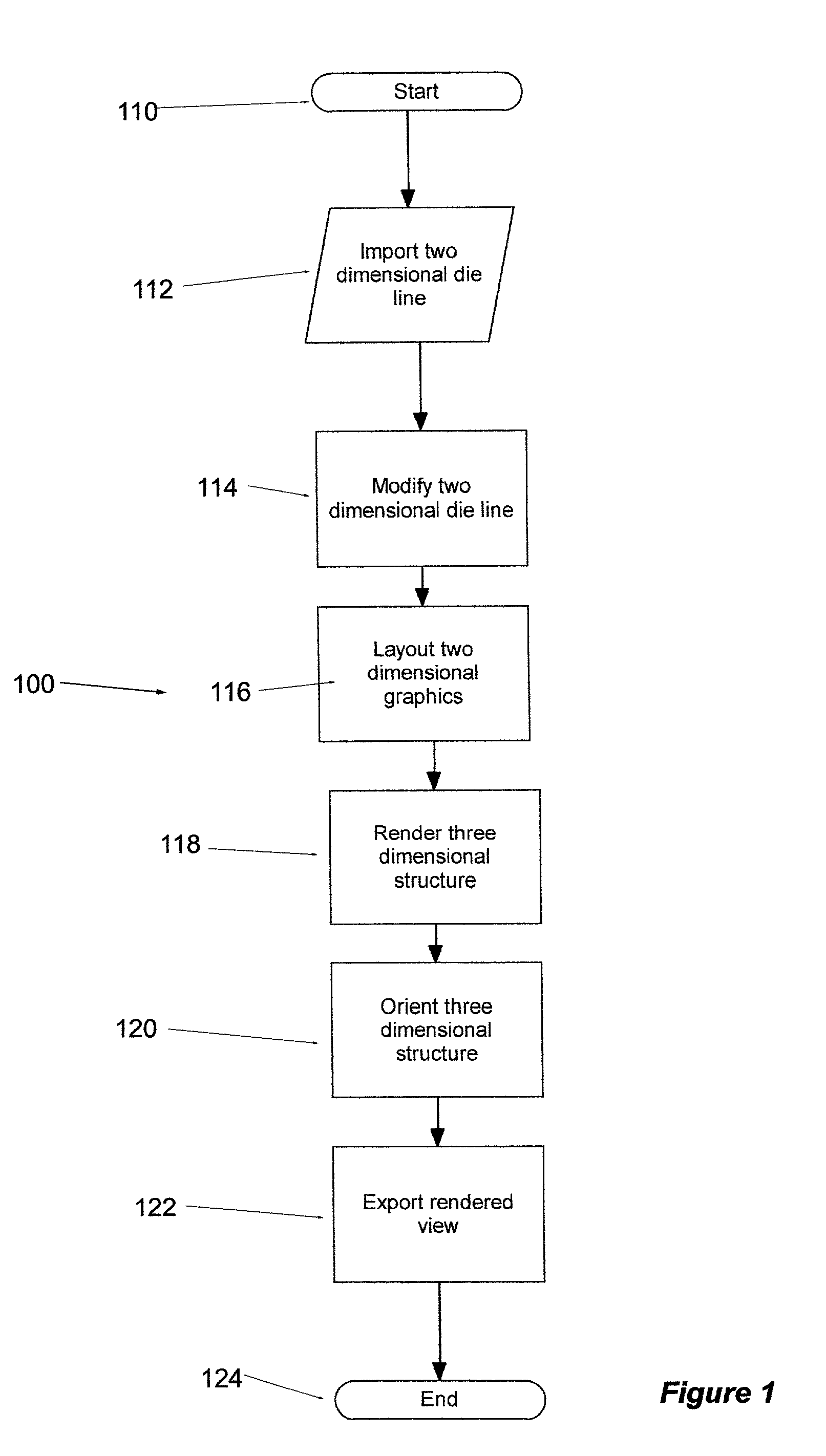
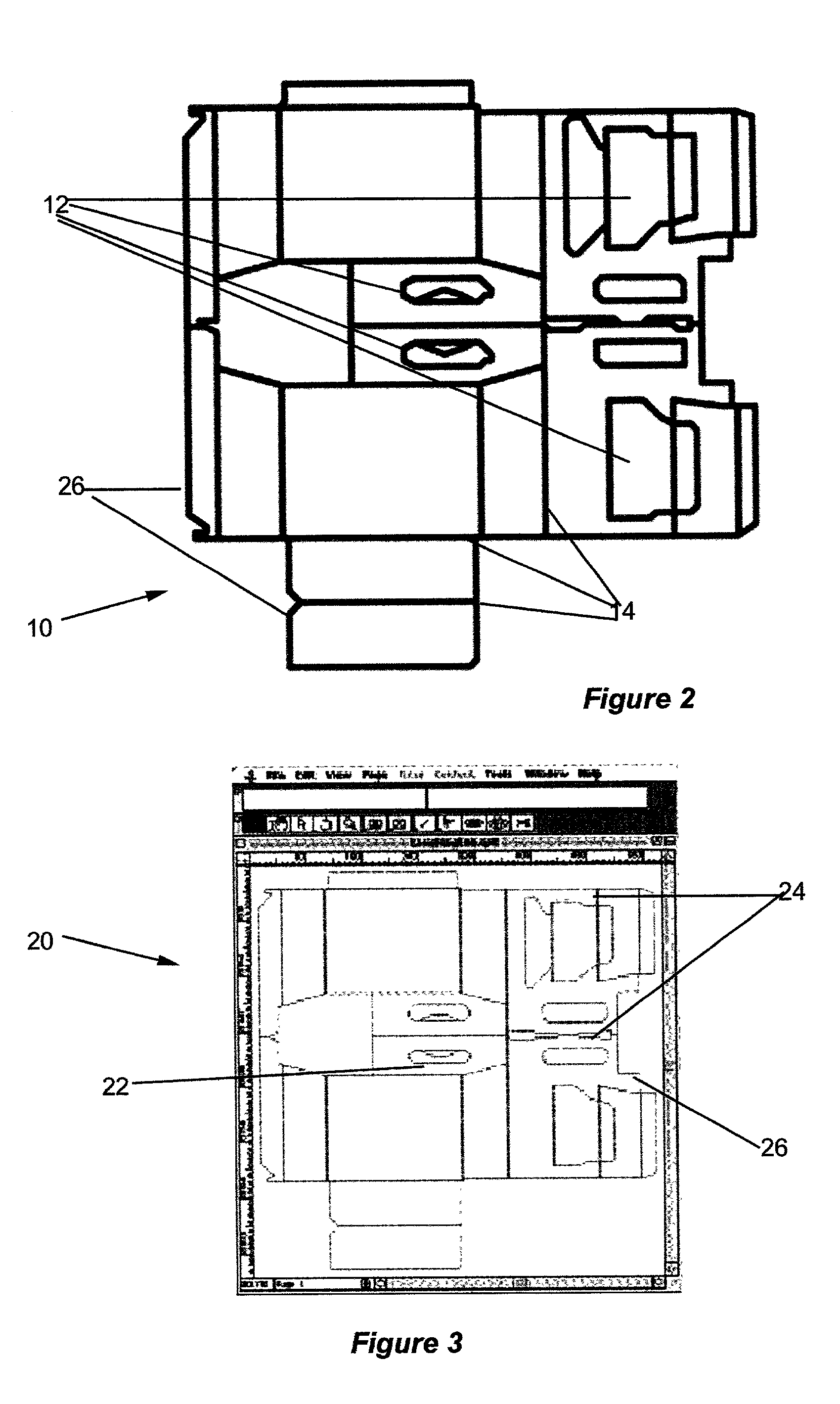
[0028] An implementation of a preferred embodiment of the present invention is illustrated in FIGS. 1-12. An overview of this preferred embodiment is illustrated in the flowchart in FIG. 1. Initially, a structural die-line drawing, such as drawing 10 in FIG. 2 is either created directly in the system, or more typically, created on Computer Aided Design software and saved in EPS format. The system, as shown at 112, is able to import the die lines of this drawing. The drawing can be opened into the system, as shown in FIG. 3. The two-dimensional structural die-line dr...


PUM


Abstract

A system and process for creating three-dimensional renderings of packaging designs. The system is able to import two-dimensional die lines and convert them into two-dimensional structural drawing. The cut lines, crease lines and boundary lines are converted into guide lines to allow design elements to be added to the drawing. Three-dimensional views can then be rendered from this two-dimensional structural drawing. Modifications to the design can be made and saved. The three-dimensional views can be exported for viewing.

Description

RELATED APPLICATIONS [0001] This application is related to subject matter of provisional application 60 / 226,802, filed on Aug. 21, 2000.FIELD OF THE INVENTION [0002] This invention relates to the field of packaging design and particularly to the field of graphically designing packaging from a layout drawing. BACKGROUND OF THE INVENTION [0003] The design of packaging for products has become an important marketing tool. The presentation of the product packaging provides a critical impact in the appeal of the product to the consumer. The design of the product packaging includes input from structural engineers to graphic designers to marketing personnel to clients and others. Previously, the engineer would design a structural container and create a physical mock-up. The graphic designer would then cut and paste design elements on the mock-up for evaluation. Changes would require another physical mock-up. This process was cumbersome and time-consuming. [0004] Tools were created to automa...

Claims


Application Information

Patent Timeline
IPC IPC(8): B65D5/42G06T15/00G06T17/40
CPCB65D5/4216G06T2219/021G06T19/00
Inventor BAIRD, ANDREW
Owner QUARK INC
Why Eureka
Try Eureka