
Iron golf club

a golf club and iron technology, applied in the field of iron golf clubs, can solve the problems of reducing vibration, low center of gravity, and reducing vibration, so as to reduce vibration, reduce vibration, and reduce the effect of high moment of inertia

Inactive Publication Date: 2005-08-04
TOPGOLF CALLAWAY BRANDS CORP
View PDF35 Cites 25 Cited by
  • Summary
  • Abstract
  • Description
  • Claims
  • Application Information

AI Technical Summary

Benefits of technology

[0018] The present invention provides an iron golf club head which has a low center of gravity, a high moment of inertia, reduced vibrations and a solid feel and appearance. The present invention is able to provide these features through use of a multiple material iron club head.

Problems solved by technology

Unfortunately, these desires are often in conflict with each other as it pertains to an iron.
The prior art fails to disclose an iron golf club head that is composed of multiple materials, has a low center of gravity, reduced vibrations, and a greater moment of inertia.

Method used


Image

  • Iron golf club
  • Iron golf club
  • Iron golf club

Examples


first embodiment

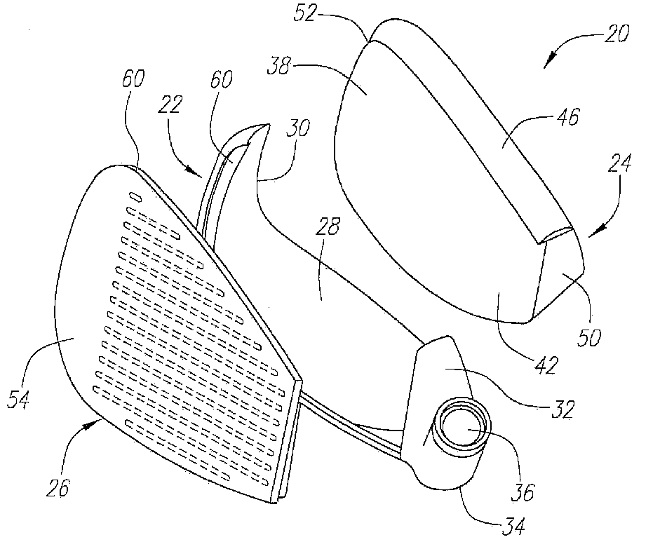
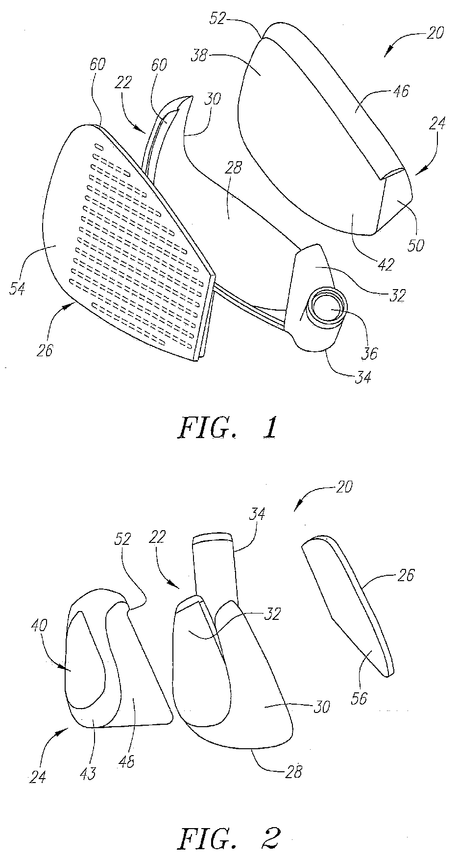
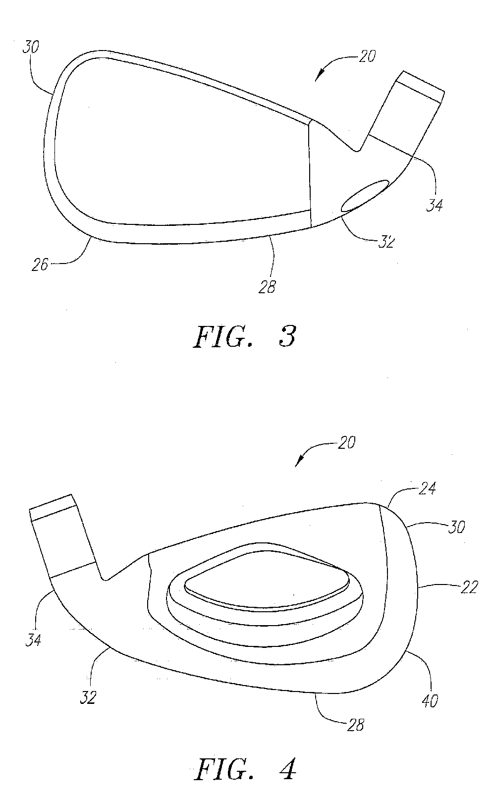
[0042] As shown in FIGS. 1-8, an iron golf club head in accordance with the present invention is generally designated 20. The club head 20 is preferably composed of three main components: a periphery member 22, a central member 24 and a face plate 26. The club head 20 can range from a 1-iron to a lob-wedge, with the loft angle preferably ranging from fifteen degrees to sixty degrees. The three main components are assembled into the club head 20 using a process such as disclosed in co-pending U.S. patent application Ser. No. 10 / 065,150, filed on Sep. 20, 2002, entitled Method For Manufacturing Iron Golf Club Head, which is hereby incorporated by reference in its entirety.

[0043] The periphery member 22 is preferably composed of a material having a density greater than 7.86 grams per centimeter cubed (“g / cm3”). A preferred material is an iron-nickel-tungsten alloy having a density preferably ranging from 8.0 g / cm3 to 12.0 g / cm3, more preferably ranging from 9.0 g / cm3 to 10.5 g / cm3. Ano...

second embodiment

[0059]FIGS. 13-20 illustrate an iron golf club head in accordance with the present invention 20′. The iron golf club head 20′ includes a periphery member 22′ composed of a material having a density greater than 7.86 g / cm3, a central member 24′ composed of a non-metal material, and a face plate 26 composed of a metal material having a lower density than the material of the periphery member 22′.

[0060] The periphery member 22′ is similar to the periphery member 22 of the first embodiment and has a sole wall 28, a toe wall 30, a heel wall 32, and a hosel 34 with a bore 36 for receiving a shaft. In addition, the periphery member 22′ has a top wall 62, which extends from an upper end of the toe wall 30 to an upper end of the heel wall 32. The top wall 62, sole wall 28, toe wall 30 and heel wall 32 define an opening 64 through the periphery member 22′. The periphery member 22′ has similar dimensions for sole wall 28, toe wall 30, and heel wall 32 as periphery member 22 of the club head 20 ...


PUM


Abstract

The iron golf club head (20) of the present invention is preferably composed of three main components: a periphery member 22, a central member 24 and a face plate 26. The periphery member (22) is preferably composed of a high density material such as a nickel-tungsten alloy. The central member (24) is preferably composed of a lightweight, non-metal material. The face plate (26) is preferably composed of a titanium alloy material. The iron golf club head (20) preferably has high moments of inertia Izz and Ixx.

Description

CROSS REFERENCE TO RELATED APPLICATIONS [0001] The present application is a continuation of co-pending U.S. patent application Ser. No. 10 / 604,520, filed on Jul. 28, 2003, which is a continuation-in-part of U.S. patent application Ser. No. 10 / 065,147, filed on Sep. 20, 2002, now U.S. Pat. No. 6,769,998.BACKGROUND OF THE INVENTION [0002] 1. Field of the Invention [0003] The present invention relates to an iron golf club. More specifically, the present invention relates to a multiple material iron golf club. [0004] 2. Description of the Related Art [0005] Irons are typically composed of a stainless steel or titanium material, and are typically cast or forged. Most golfers desire that their irons have a large sweet spot for greater forgiveness, a low center of gravity to get the ball in the air, a solid sound, reduced vibrations during impact, and a trim top line for appearance. Unfortunately, these desires are often in conflict with each other as it pertains to an iron. [0006] The use...

Claims


Application Information

Patent Timeline
Patent Type & Authority Applications(United States)
IPC IPC(8): A63B53/04A63B59/00
CPCA63B53/0466A63B53/047A63B59/0092A63B2053/0408A63B2053/042A63B2053/0433A63B2209/00A63B2209/02A63B2053/0416A63B60/54A63B53/042A63B53/0408A63B53/0416A63B53/0433
Inventor REYES, HERBERTDESHMUKH, UDAY V.LANG, ROBERT R.BOLANE, JESSEWIELAND, CHRIS J.
Owner TOPGOLF CALLAWAY BRANDS CORP
Learn More