
Display frame

a display frame and frame technology, applied in the field of frames, can solve the problems of reducing display area and high assembly cost, and achieve the effect of improving frame stability

Inactive Publication Date: 2005-08-11
TRAINERS WAREHOUSE
View PDF5 Cites 2 Cited by
  • Summary
  • Abstract
  • Description
  • Claims
  • Application Information

AI Technical Summary

Benefits of technology

[0005] According to another feature, the invention includes an attachment mechanism permanently securing the first sheet member to the second sheet member. The attachment mechanism preferably consists of welds formed between the top and bottom side wall portions and between the bottom side wall portions and the inner top wall surface. The attachment mechanism further enhances frame stability.
[0006] According to yet another feature of the invention, the total width of the second sheet member between outer edges of the bottom side wall portions and the outer bottom wall surface is substantially equal to a uniform length of the top side wall portions. This feature contributes to the creation of a smooth frame profile.
[0008] According to further features of the invention, the width W of the first sheet member between internal surfaces of a parallel pair of the top wall portions is equal to the total width W of the second sheet member between external surfaces of a parallel pair of the bottom side wall portions; and the length L of the first sheet member between the particular connected edge and an internal surface of the top wall portion parallel thereto is equal to a total length L of the second sheet member between joined edges thereof lying parallel to the particular connected edge. These features further contribute to a smooth frame profile.

Problems solved by technology

Disadvantages of such a frame include high assembly costs and reduced display area because of the marginal regions occupied by the spacer elements.

Method used


Image

  • Display frame
  • Display frame
  • Display frame

Examples


Embodiment Construction

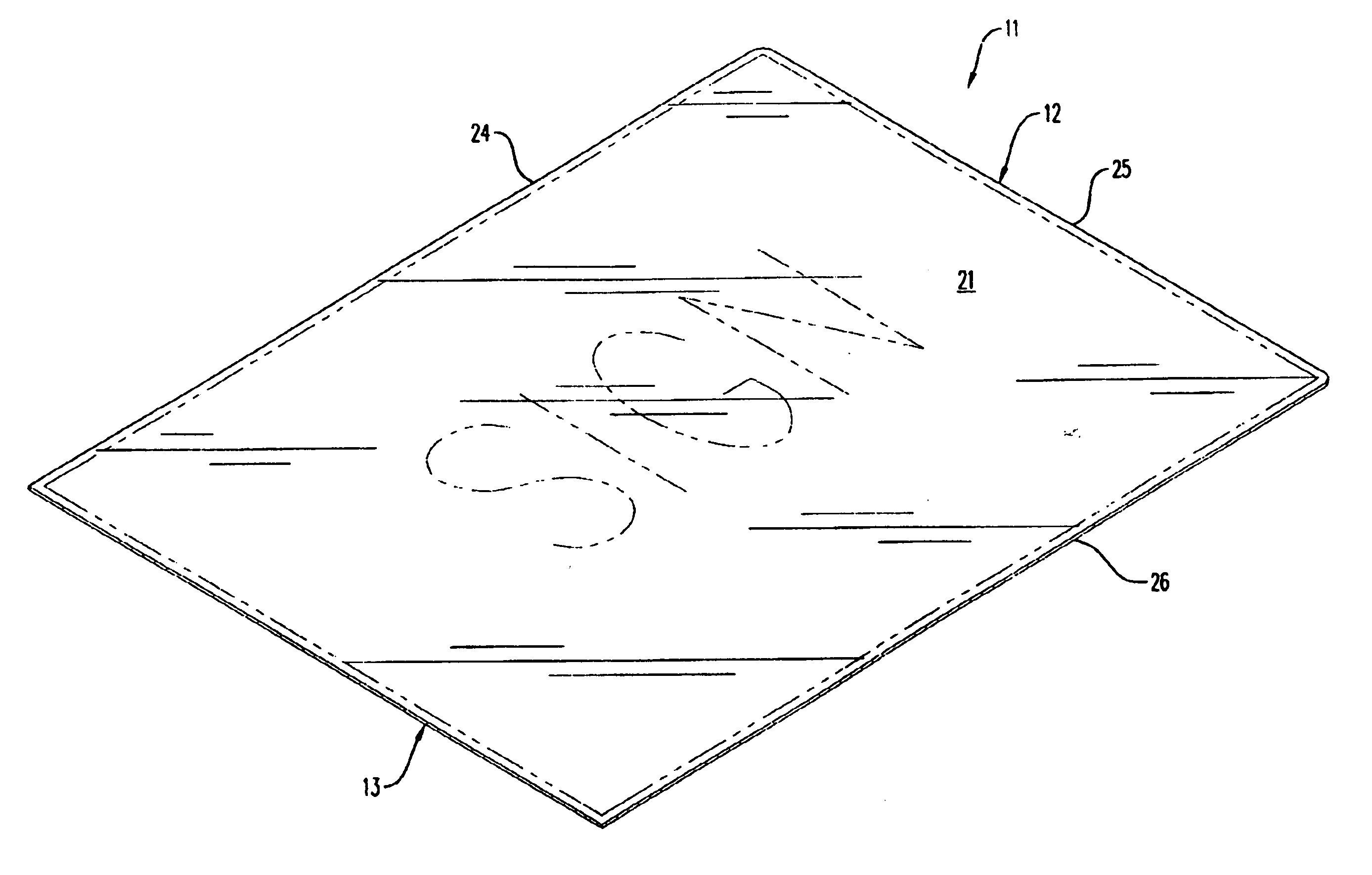
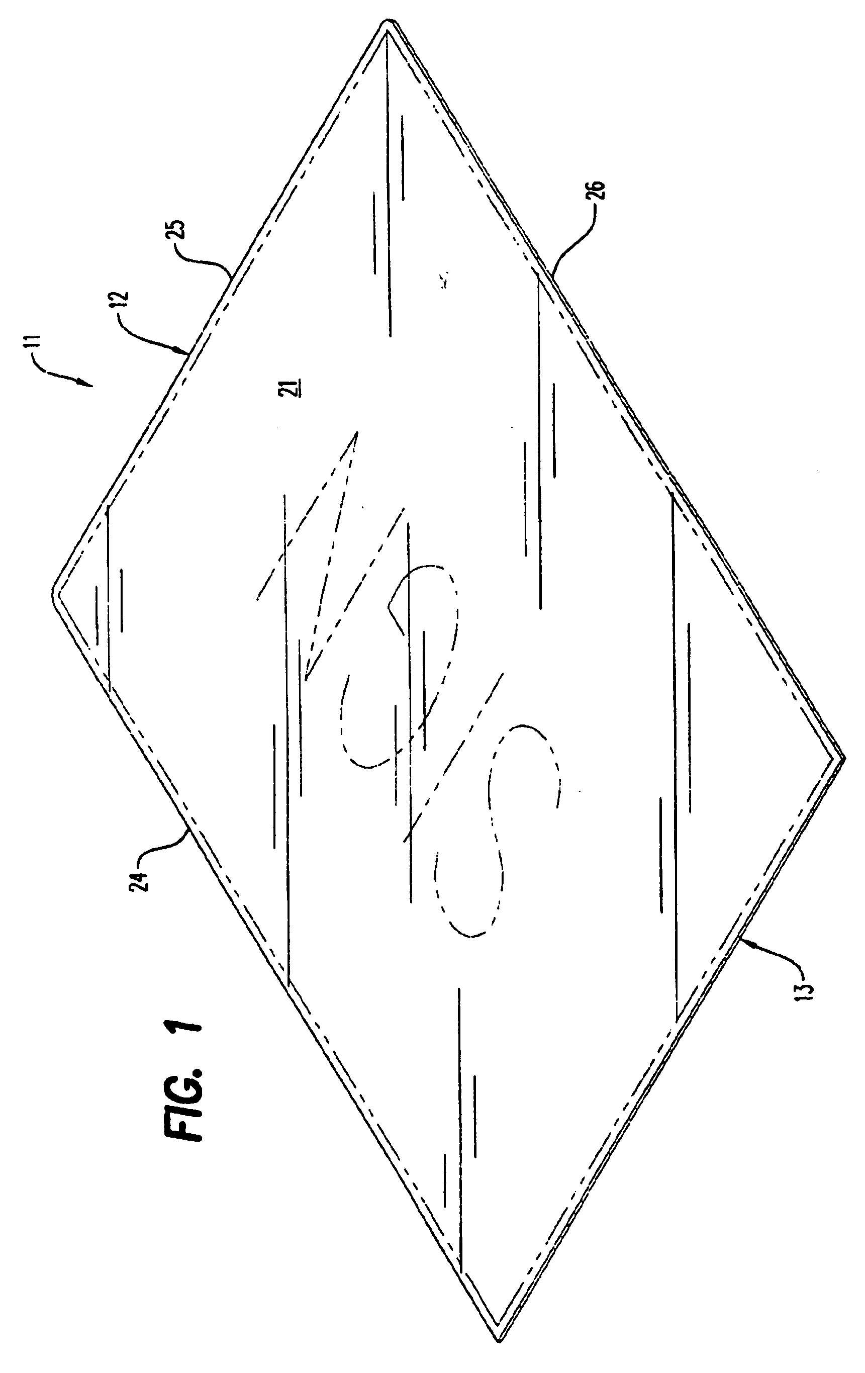
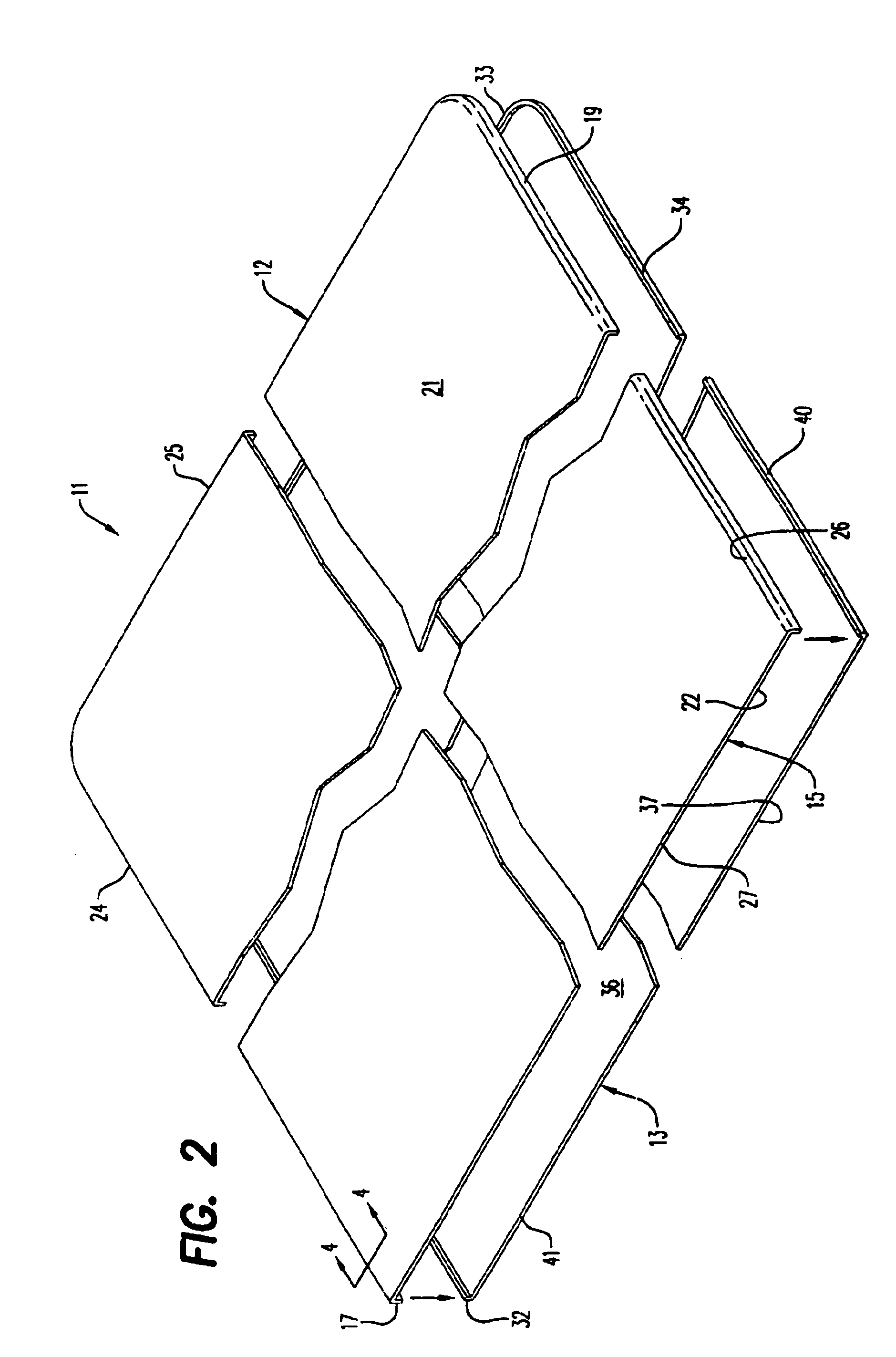
[0017] A frame 11 is provided by the assembly of a first sheet member 12 and a second sheet member 13 as shown in FIG. 1. Forming the first sheet member 12 is a top wall portion 15 and a plurality of top side wall portions 17-19. The top wall portion 15 has a rectangular inner top wall surface 21 and a rectangular outer top wall surface 22 defined by rectilinear connected edges 24-27. As illustrated in FIGS. 2-5, the side wall portions 17-19 extend outwardly from the inner top wall surface 22 and one of the side wall portions 17-19 is aligned with each of the connected edges 24-26 except one particular edge 27.

[0018] The second sheet member 13 is formed by a bottom wall portion 31 and a plurality of bottom side wall portions 32-34. Defining the bottom wall portion 31 are a rectangular inner bottom wall surface 36 and a rectangular outer bottom wall surface 37 having rectilinear joined edges 38-41 lying parallel to the connected edges 24-27. The bottom side wall portions 32-34 are d...


PUM


Abstract

A frame including a first sheet member having a transparent top wall portion with an inner top wall surface and an outer top wall surface defined by rectilinear connected edges and a top side wall portion aligned with each of the rectilinear connected edges other than a particular one thereof. Also included is a second sheet member having a bottom wall portion with an inner bottom wall surface and an outer bottom wall surface defined by rectilinear joined edges extending parallel to the connected edges, and a bottom sidewall portion extending outwardly from said inner bottom wall surface and disposed parallel to and inwardly laterally adjacent to each of the top side wall portions so as to form between the inner top wall surface and the inner bottom wall surface a closed cavity accessible through an opening adjacent to the particular connected edge.

Description

FIELD OF THE INVENTION [0001] The invention relates generally to a frame and, more particularly, to an assembly of molded plastic transparent sheets for sandwiching a sign, photograph, display or the like. BACKGROUND OF THE INVENTION [0002] Frames made of transparent plastic sheets for retaining display sheets are well known. Examples of such a frame are disclosed, for example only, in U.S. Pat. Nos. 4,726,132 and 5,058,300 Also known is a frame consisting of thin transparent sheets secured together along three inner marginal edges with spacer elements creating between the sheets a cavity for receiving a display sheet. Disadvantages of such a frame include high assembly costs and reduced display area because of the marginal regions occupied by the spacer elements. The object of this invention, therefore, is to provide an improved plastic sheet frame assembly. SUMMARY OF THE INVENTION [0003] The invention is a frame including a first sheet member having a transparent top wall portion...

Claims


Application Information

Patent Timeline
Patent Type & Authority Applications(United States)
IPC IPC(8): G09F1/12G09F3/18G09F15/00
CPCG09F15/0012G09F1/12
Inventor DOCTOROFF, MICHAEL
Owner TRAINERS WAREHOUSE
Learn More