Frame for the drive unit of an industrial truck, particularly a stacker lift truck

a technology for industrial trucks and drive units, which is applied in the direction of lifting devices, hand carts, understructures, etc., can solve the problems of not insignificant manufacturing expenditure, and achieve the effects of reducing mounting expenditure, low manufacturing cost, and improving product quality

Inactive Publication Date: 2006-06-06
JUNGHEINRICH AG
View PDF12 Cites 3 Cited by
  • Summary
  • Abstract
  • Description
  • Claims
  • Application Information

AI Technical Summary

Benefits of technology

[0006]The inventive frame comprises a forward-facing apron formed in the shape of a bow from a cut-to-size flat sheet metal piece, which defines the lower front and lateral visible surface of the industrial truck, and a one-piece rear wall formed from a cut-to-size flat sheet metal piece that is connected to the apron. The rear wall serves as a carrier unit for attachment and installation parts in the drive unit. It has upper and lateral portions formed by chamfers which also define visible surface portions of the casing for the drive unit. The parts described, along with particular carriers which are preferably formed from thicker sheet metal pieces and are welded to the rear wall, reduce the overall number of the parts to be joined by welding to a very low degree, which significantly reduces the mounting expenditure. A reduction in the number of welds and lengths of the welds also improves the product quality with the cost of manufacture being low.

Problems solved by technology

The disadvantage of conventional drive frames is that they are made of a series of single parts which are welded together.
The large number of welded components and, hence, the considerable length of the welds result in a manufacturing expenditure which is not insignificant.

Method used


Image

  • Frame for the drive unit of an industrial truck, particularly a stacker lift truck
  • Frame for the drive unit of an industrial truck, particularly a stacker lift truck
  • Frame for the drive unit of an industrial truck, particularly a stacker lift truck

Examples


Embodiment Construction

[0019]While this invention may be embodied in many different forms, there are described in detail herein a specific preferred embodiment of the invention. This description is an exemplification of the principles of the invention and is not intended to limit the invention to the particular embodiment illustrated

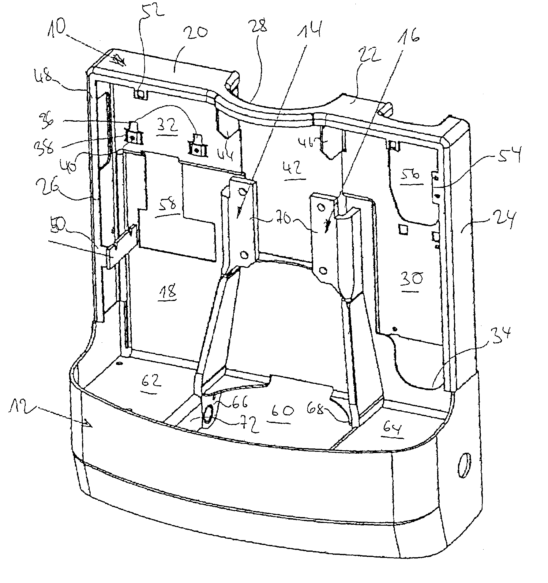
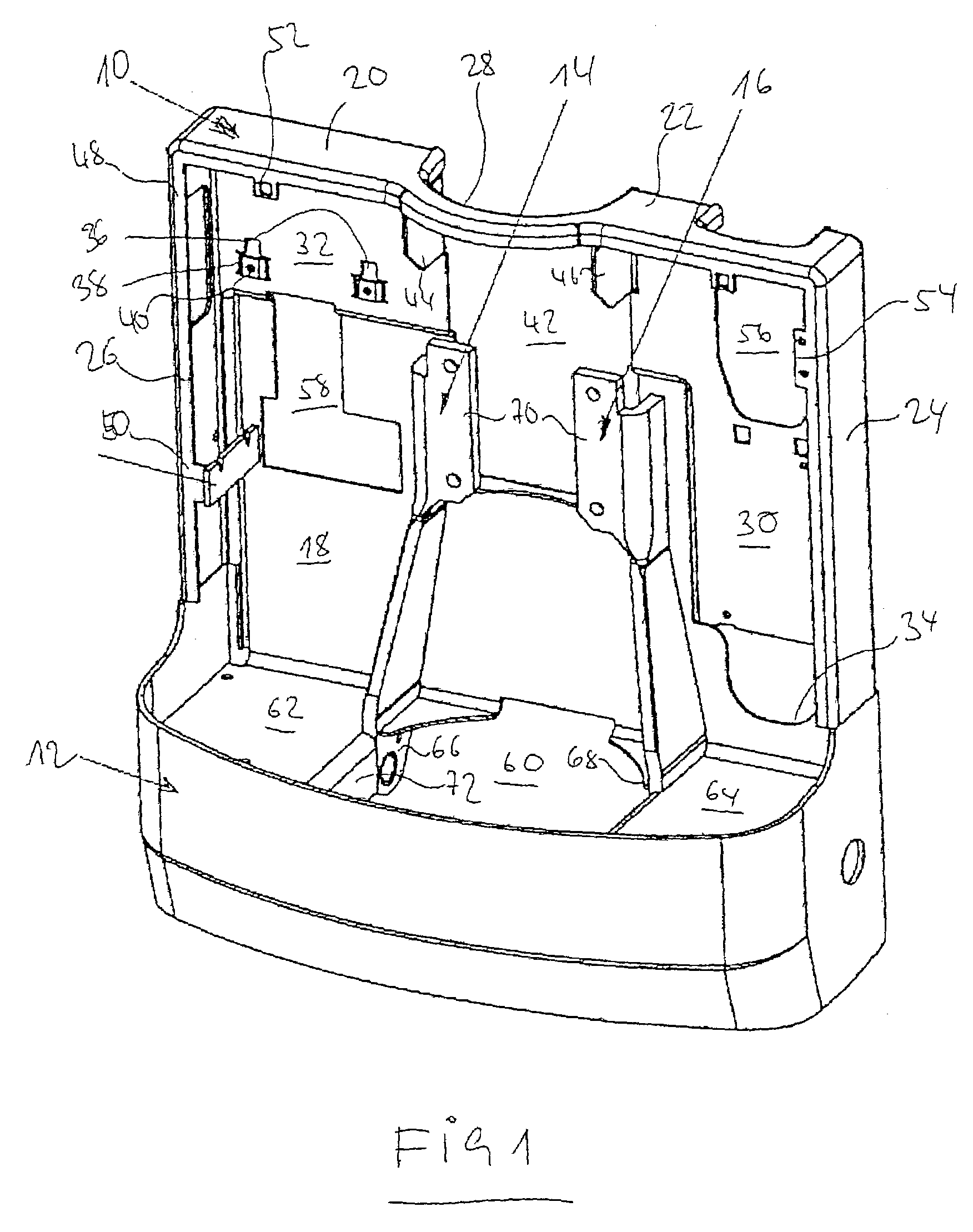
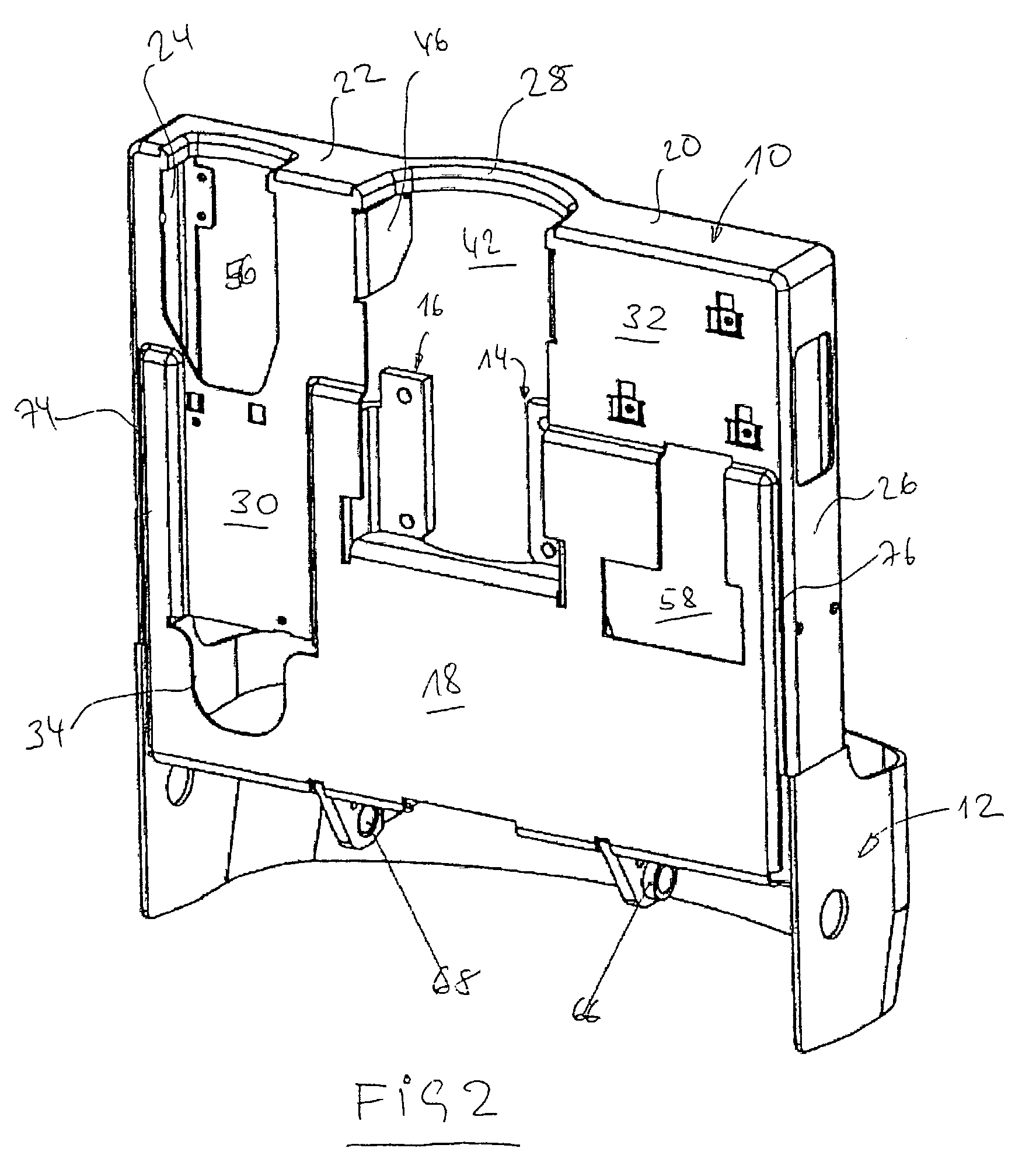
[0020]The frame illustrated in FIGS. 1 and 2 substantially comprises four single components, i.e. a box-like rear wall 10, a bow-shaped apron 12, and two carrier elements 14, 16 which are welded to the front of the rear wall 10. Reference will now be made in detail to the individual components.

[0021]The rear wall 10 has a rear wall portion 18 from the extension of which flange-like upper portions 20, 22 and lateral portions 24, 26 are bent away to the front approximately at right angles. Portions 22, 24, on one hand, and 20, 26, on the other, merge into each other and portions 20, 22 are interconnected by a forwardly bent arc-shaped web 28. The portions 18 to 28 described are ...


PUM


Abstract

A frame for the drive unit of an industrial truck, particularly a stacker lift truck which, inter alia, serves as a carrier of a lifting device and/or travel drive. The frame having a forward-facing apron formed in the shape of a bow from a cut-to-size flat sheet metal piece and a one-piece rear wall formed from a cut-to-size flat sheet metal piece connected to the apron as a carrier unit for attachment and installation parts in the drive unit, which is chamfered and, as a result, has an upper portion and lateral portions which also define visible surface portions of the casing for the drive unit.

Description

CROSS-REFERENCE TO RELATED APPLICATIONS[0001]Not Applicable.STATEMENT REGARDING FEDERALLY SPONSORED RESEARCH[0002]Not Applicable.BACKGROUND OF THE INVENTION[0003]A frame of the generic type has become known from DE 299 18 832 U1. The frame is intended for receiving forces of a lifting device and for receiving forces of at least one wheel of the industrial truck and its drive and has two perpendicularly disposed plates which are oriented in parallel with the longitudinal axis of the industrial truck and are spaced from each other in the transverse direction of the industrial truck.[0004]The disadvantage of conventional drive frames is that they are made of a series of single parts which are welded together. The large number of welded components and, hence, the considerable length of the welds result in a manufacturing expenditure which is not insignificant.[0005]It is the object of this invention to provide a frame for the drive unit of an industrial truck that is made of a minimum n...

Claims


Application Information

Patent Timeline
Patent Type & Authority Patents(United States)
IPC IPC(8): B62D21/00B62B3/06B66F9/075
CPCB66F9/07513B62B3/0612
Inventor LOHMANN, HELMUT
Owner JUNGHEINRICH AG
Why Eureka
Try Eureka