
Air Filter System of a Motor Vehicle

a technology of air filter system and motor vehicle, which is applied in the direction of filtration separation, auxillary pretreatment, separation process, etc., can solve the problems of inability to meet the requirements of the motor, etc., to achieve the effect of improving the measuring precision, increasing the measuring precision, and improving the accuracy of motor control action

Active Publication Date: 2010-01-28
MANN HUMMEL GMBH
View PDF18 Cites 12 Cited by
  • Summary
  • Abstract
  • Description
  • Claims
  • Application Information

AI Technical Summary

Benefits of technology

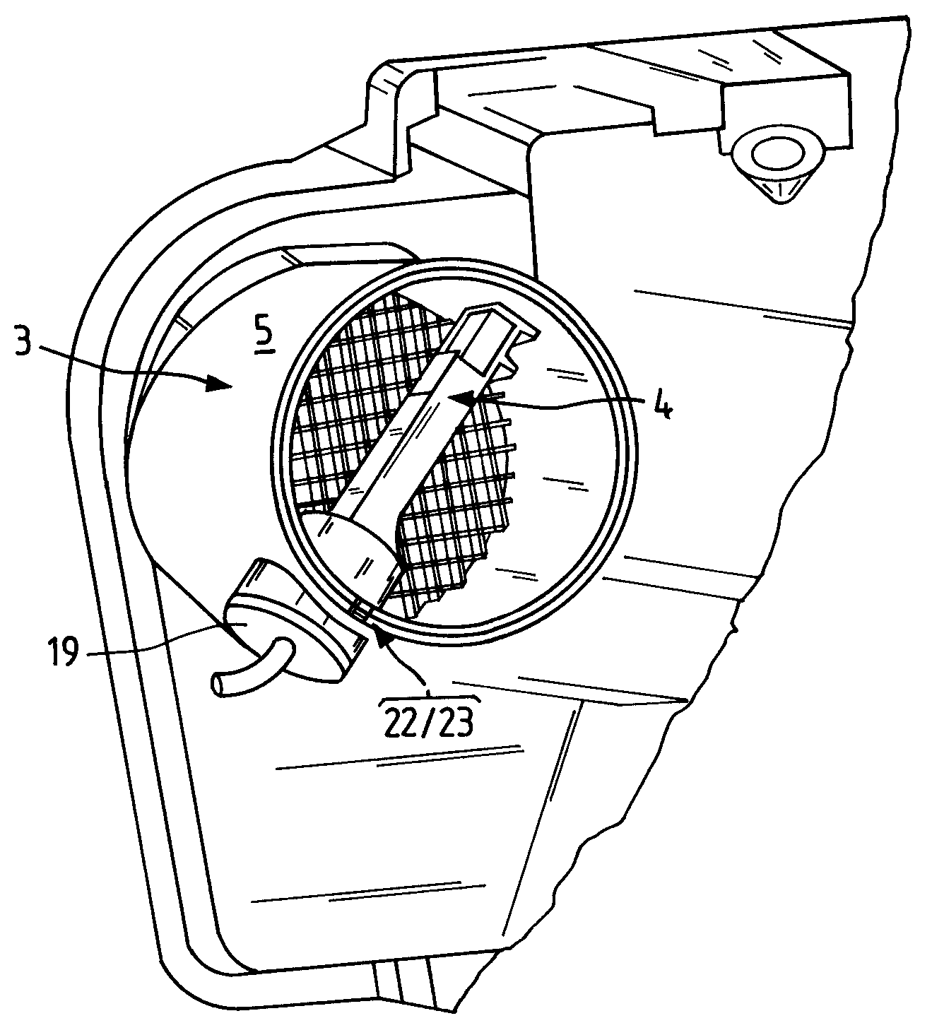
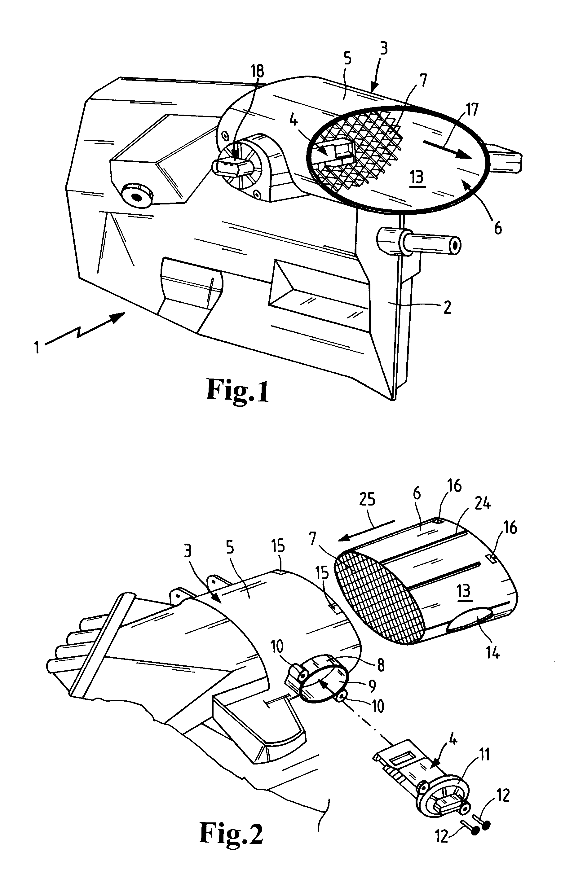
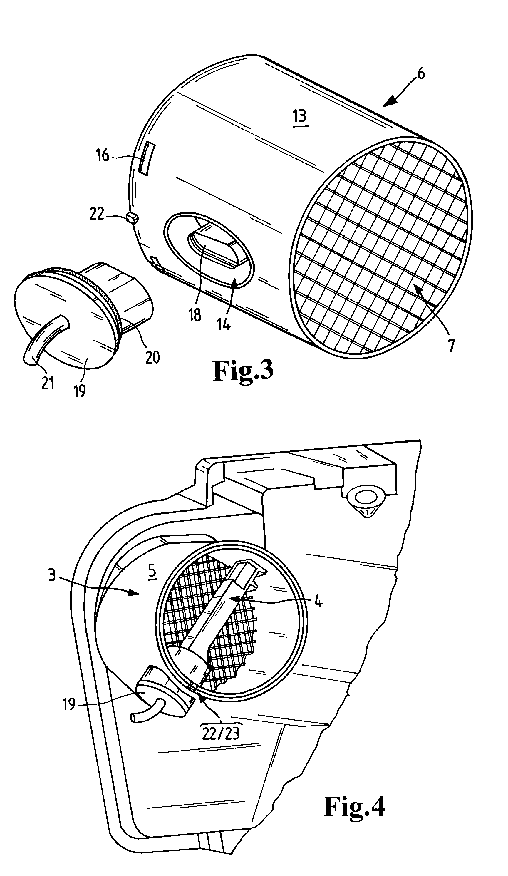
[0011]In deviation from the known configuration of a HF MAF sensor with a housing, the integrally formed same-material molding of the circumferentially extending passage wall on the housing part of the air filter housing, which passage wall forms the air passage section, has the result that no cross-sectional losses are produced by an otherwise existing interface to the air filter housing so that the desired minimal pressure loss in the intake air flow is achieved. Also, the disadvantages of the known configuration with a plug-in HF MAF sensor without its own housing are eliminated: The housing part of the air filter housing can still be produced from a suitable plastic material such as polyamide (PA). The moisture-sensitivity observed in connection with this plastic material in the form of water absorption and resulting dimensional changes no longer has a disadvantageous effect on the measuring precision of the mass air flow sensor arranged in the air passage section. Instead, the lining at the inner side of the passage wall of the air passage section by means of the plastic insert of moisture-insensitive plastic material provides for dimensional stability of the passage cross-section and thus of the geometric flow course that is, at least in approximation, independent of the moisture of the ambient air and of the intake air flow. Moisture effects on the flow course of the intake air flow and thus on the measuring result of the mass air flow sensor are thus almost completely prevented. In comparison to an insert in the form of a sheet metal part that is punch-riveted, a smooth aerodynamically shaped and interference-free surface can be produced because of the elimination of rivets, abutting edges or the like which surface is beneficial for obtaining a laminar flow about the mass air flow sensor and thus contributes to improving the measuring precision. As a whole, a significantly increased measuring precision is produced that is beneficial for a more precise motor control action.
[0012]The preferred material pairing of PA for the housing part of the filter housing and PBT for the plastic insert is based on the excellent material compatibility of both plastic materials because PA and PBT have similar thermal expansion coefficients. The very minimal water absorption of PBT however eliminates at least in approximation the moisture effect on dimensional changes of the passage cross-section and thus on the geometric flow course of the intake air flow.
[0013]It can be expedient to introduce the plastic insert, for example, by means of a two-component injection molding process, into the air passage section. In a preferred embodiment, the plastic insert is inserted into the air passage section and in particular locked in place therein. Manufacturing and mounting expenditures are minimized. The insertion and also the locking action, on the one hand, produce a precise positional fixation of the plastic insert while, one on the other hand, there exists no intimate material connection between the two components. Moisture-caused dimensional changes of the passage wall of the air passage section are not forced onto the plastic insert.
[0014]In a preferred embodiment, an air guiding grid is formed integrally with the plastic insert. In particular, the plastic insert is injection-molded. The integral (monolithic) configuration of the air guiding grid with the plastic insert generates not only a reduction of the number of individual parts and thus a reduction of the mounting expenditure; in addition, the positional tolerances of the individual parts relative to one another are improved so that the measuring precision is improved also. In comparison to e.g. a metallic component, the manufacture of the plastic insert by an injection-molding method increases in addition to the dimensional precision also the degrees of freedom with regard to shaping. For example, an aerodynamically rounded intake area can be integrally formed that contributes to a laminar flow and thus is beneficial also in regard to measuring precision of the mass air flow sensor.

Problems solved by technology

Such configurations however incur comparatively high costs.
Moreover, the interface of HF MAF sensor housing and air filter housing causes a reduction of the free flow cross-section so that an undesirably increased pressure loss in the intake air flow is observed.
However, in this connection several difficulties have to be overcome.
In this connection, in addition to the unavoidable thermal dimensional changes also moisture-caused dimensional changes occur because polyamide, as a moisture-sensitive plastic material, has the tendency to absorb moisture.
The moisture-caused dimensional changes of the air passage section supporting the mass air flow sensor cannot be compensated easily.
As a result, moisture-caused dimensional changes of the air passage section affect the geometric flow course and thus cause measuring errors or measuring imprecisions.
A possibly required flow guiding grid that is provided for calming the flow or for causing laminar flow of the intake air flow and that contributes therefore to measuring precision must be manufactured and mounted as a separate component; this is not optimal with regard to costs and also generates additional dimensional tolerances.

Method used


Image

  • Air Filter System of a Motor Vehicle
  • Air Filter System of a Motor Vehicle
  • Air Filter System of a Motor Vehicle

Examples


Embodiment Construction

[0024]Before describing in detail embodiments that are in accordance with the present invention, it should be observed that the embodiments reside primarily in combinations of method steps and apparatus components related to an air filter system for a motor vehicle as disclosed herein. Accordingly, the apparatus components and method steps have been represented where appropriate by conventional symbols in the drawings, showing only those specific details that are pertinent to understanding the embodiments of the present invention so as not to obscure the disclosure with details that will be readily apparent to those of ordinary skill in the art having the benefit of the description herein.

[0025]In this document, relational terms such as first and second, top and bottom, and the like may be used solely to distinguish one entity or action from another entity or action without necessarily requiring or implying any actual such relationship or order between such entities or actions. The ...


PUM

PropertyMeasurementUnit
axial lengthaaaaaaaaaa
mass air flowaaaaaaaaaa
pressure lossaaaaaaaaaa

Abstract

An air filter system of a motor vehicle has an air filter housing with a housing part of a moisture-sensitive plastic material and an air passage section with a circumferentially extending passage wall, wherein the passage wall of the air passage section is integrally formed of identical material on the housing part of the air filter housing. A mass air flow sensor is arranged in the air passage section. A plastic insert of a moisture-insensitive plastic material is disposed on an inner side of the passage wall of the air passage section and lines the passage wall.

Description

CROSS REFERENCE TO RELATED APPLICATIONS[0001]This application claims the benefit under 35 USC 119 of the filing date of foreign application DE 20 2008 010 058.5 filed in the Federal Republic of Germany on Jul. 25, 2008, the entire disclosure of which is incorporated herein by reference.TECHNICAL FIELD[0002]This disclosure relates to an air filter system of a motor vehicle.BACKGROUND OF THE INVENTION[0003]The invention relates an air filter system of a motor vehicle, comprising an air filter housing with a housing part of moisture-sensitive plastic material and an air passage section with a circumferentially extending passage wall, wherein the passage wall of the air passage section is integrally formed of identical material on the housing part of the air filter housing and wherein a mass air flow sensor is arranged in the air passage section.[0004]Internal combustion engines of a motor vehicle comprise an electronic control unit in particular for metering the fuel quantity to be inj...

Claims


Application Information

Patent Timeline
Patent Type & Authority Applications(United States)
IPC IPC(8): B01D46/42B01D50/00
CPCF02M35/02F02M35/10386F02M35/024
Inventor DIRNBERGER, TIMO
Owner MANN HUMMEL GMBH
Learn More