
Lithographic apparatus and device manufacturing method

a technology of lithographic equipment and manufacturing method, which is applied in the direction of photomechanical equipment, printers, instruments, etc., can solve the problems of significant cost reduction and significant lead-time reduction

Inactive Publication Date: 2006-06-13
ASML NETHERLANDS BV
View PDF15 Cites 1 Cited by
  • Summary
  • Abstract
  • Description
  • Claims
  • Application Information

AI Technical Summary

Benefits of technology

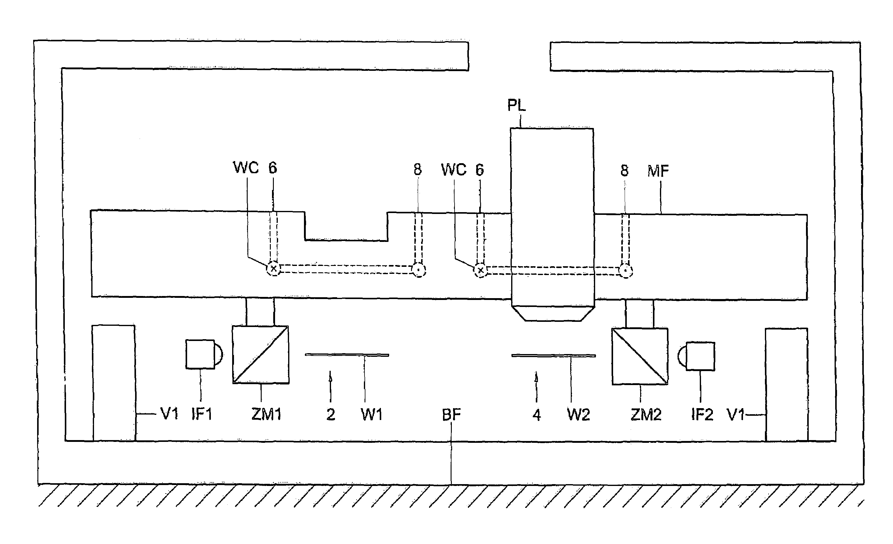
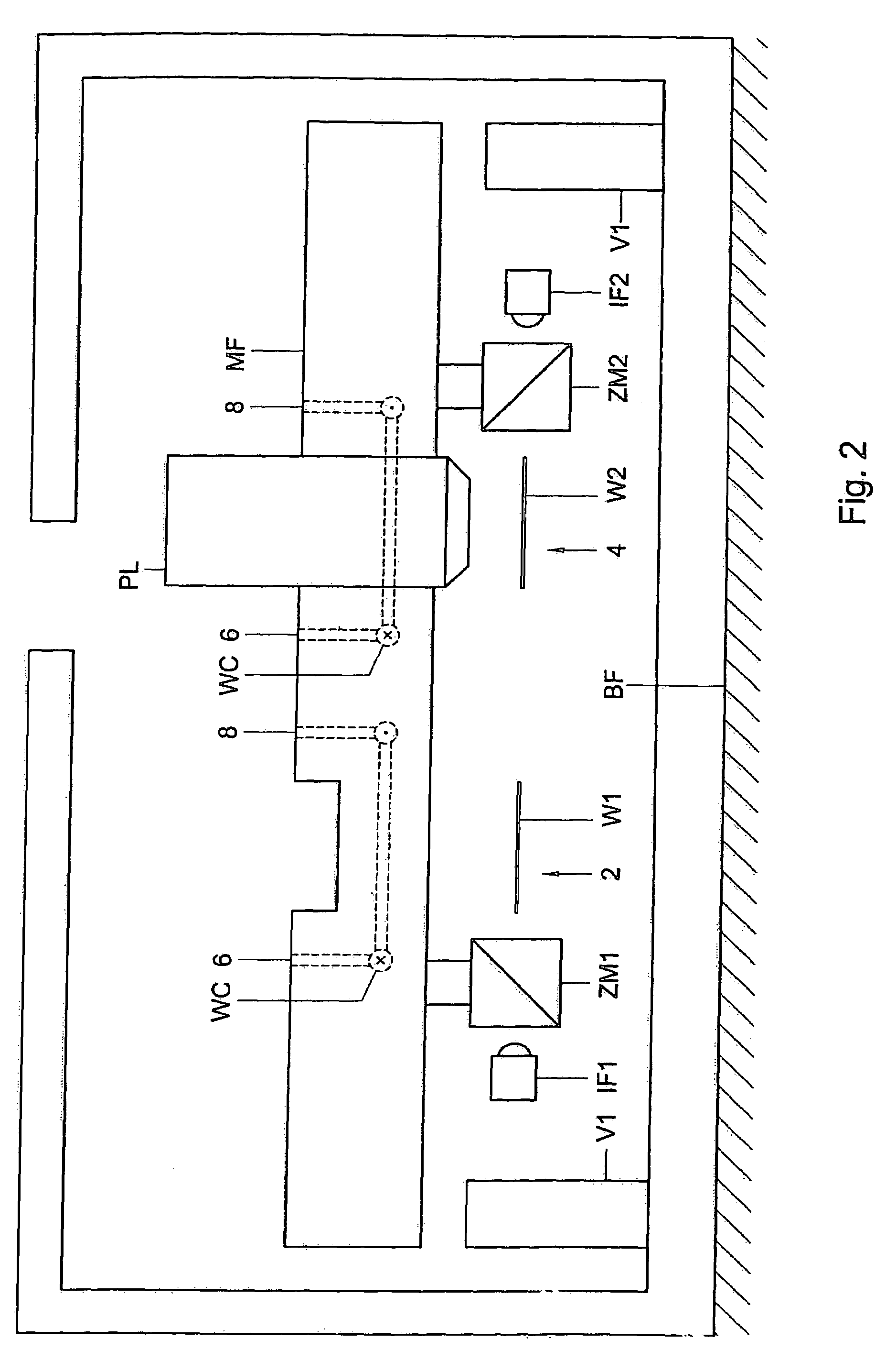
[0010]By providing a reference frame comprising a material having a high coefficient of thermal expansion a wider variety of materials are available for the reference frame. It has been found that materials, such as aluminium or aluminium alloy materials, results in a significant cost reduction and a significant lead-time decrease. Further, the present invention provides the additional surprising effect that the dynamic performance of the reference frame is equal or better than reference frames made of conventional materials, such as INVAR™. By rejecting the assumption that a reference frame must be constructed of a material having a low coefficient of thermal expansion in order to achieve the required thermal and thermo-dynamic performance, the inventors have overcome substantial technical prejudice.
[0022]By providing a reference frame of a material having a high specific heat and / or a high thermal conductivity, the thermal stability of the frame is improved.

Problems solved by technology

It has been found that materials, such as aluminium or aluminium alloy materials, results in a significant cost reduction and a significant lead-time decrease.

Method used


Image

  • Lithographic apparatus and device manufacturing method
  • Lithographic apparatus and device manufacturing method
  • Lithographic apparatus and device manufacturing method

Examples


Embodiment Construction

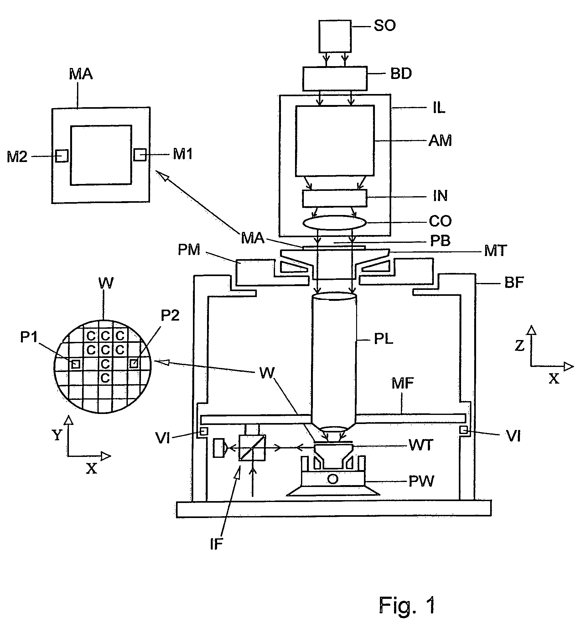
[0039]FIG. 1 schematically depicts a lithographic apparatus according to a particular embodiment of the invention. The apparatus comprises: an illumination system (illuminator) IL for providing a projection beam PB of radiation (e.g. UV radiation or EUV radiation); a first support structure (e.g. a mask table) MT for supporting a patterning structure (e.g. a mask) MA and connected to a first positioning device PM for accurately positioning the patterning structure with respect to item PL; a substrate table (e.g. a wafer table) WT for holding a substrate (e.g. a resist coated wafer) W and connected to a second positioning device PW for accurately positioning the substrate with respect to item PL; and a projection system (e.g. a refractive projection lens) PL for imaging a pattern imparted to the projection beam PB by the patterning structure MA onto a target portion C (e.g. comprising one or more dies) of the substrate W. The term “substrate table” as used herein can also be consider...


PUM

PropertyMeasurementUnit
wavelengthaaaaaaaaaa
specific heataaaaaaaaaa
thermal conductivityaaaaaaaaaa

Abstract

A lithographic apparatus is disclosed. The apparatus includes an illumination system that provides a beam of radiation, and a support structure that supports a patterning structure. The patterning structure is configured to impart the beam of radiation with a pattern in its cross-section. The apparatus also includes a substrate support that supports a substrate, a projection system that projects the patterned beam onto a target portion of the substrate, and a reference frame that provides a reference surface with respect to which a position of at least one of the substrate and the patterning structure is measured. The reference frame includes a material that has a coefficient of thermal expansion of greater than about 2.9×10⁻⁶ / K.

Description

CROSS-REFERENCE TO RELATED APPLICATIONS[0001]This application is based on and claims the benefit of priority from International Patent Application No. PCT / NL03 / 00798 filed Nov. 13, 2003, the entire contents of which are incorporated herein by reference.BACKGROUND OF THE INVENTION[0002]1. Field of Invention[0003]The present invention relates to a lithographic apparatus and a device manufacturing method.[0004]2. Description of Related Art[0005]A lithographic apparatus is a machine that applies a desired pattern onto a target portion of a substrate. Lithographic apparatus can be used, for example, in the manufacture of integrated circuits (ICs). In that circumstance, a patterning device or structure, such as a mask, may be used to generate a circuit pattern corresponding to an individual layer of the IC, and this pattern can be imaged onto a target portion (e.g. comprising part of, one or several dies) on a substrate (e.g. a silicon wafer) that has a layer of radiation-sensitive materi...

Claims


Application Information

Patent Timeline
Patent Type & Authority Patents(United States)
IPC IPC(8): G03B27/42G03B27/58G03B27/62G02B7/02H01L21/027G03F7/20
CPCG02B7/028G03F7/70833G03F7/7095G03F7/709G03F7/70858G03F7/70825G03F7/70991
Inventor BARTRAY, PERTRUS RUTGERUSBOX, WILHELMUS JOSEPHUSLUTTIKHUIS, BERNARDUS ANTONIUS JOHANNESTEN BHOMER, MICHAEL
Owner ASML NETHERLANDS BV
Learn More