Micromanipulation system

a micromanipulation and system technology, applied in the field of micromanipulation systems, can solve problems such as experience and skill, and achieve the effect of avoiding the need for vertical direction

Inactive Publication Date: 2005-08-11
OLYMPUS CORP
View PDF21 Cites 17 Cited by
  • Summary
  • Abstract
  • Description
  • Claims
  • Application Information

AI Technical Summary

Problems solved by technology

Therefore, the alignment in the vertical direction requires experience and skill, which is a problem in operation for many operators.

Method used


Image

  • Micromanipulation system
  • Micromanipulation system
  • Micromanipulation system

Examples


Embodiment Construction

The First Preferred Embodiment

[0039] In the present invention, even for a plurality of specimens each of different height, a manipulator can be automatically operated. For that purpose as an initial process, the position where the tip of a fine needle is focused in an object lens is registered as the Z-direction reference position of a manipulator driving unit.

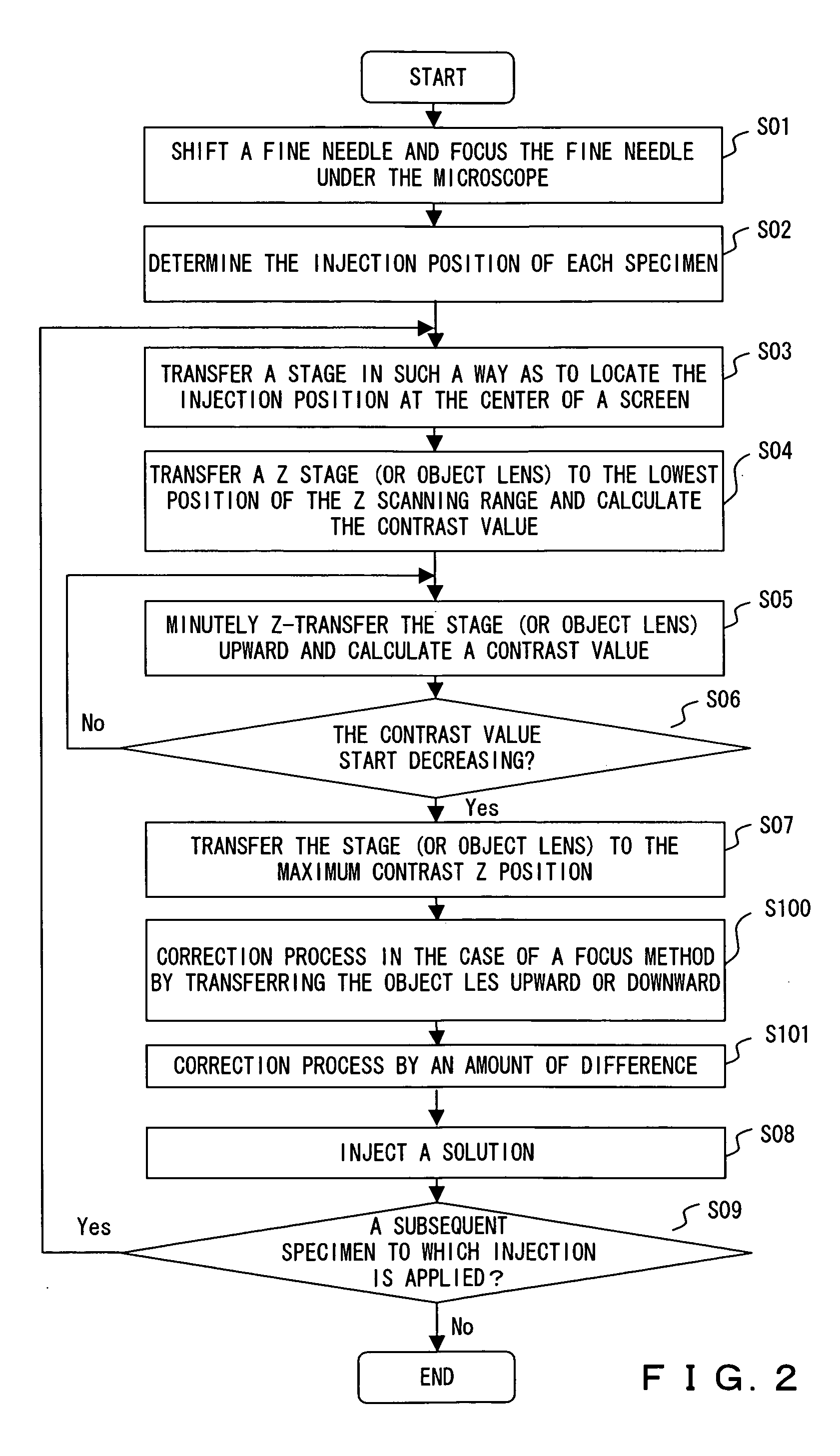
[0040] In this preferred embodiment, if each specimen has a different height, during a focusing process, the height of the injection position of each specimen is controlled so that the contrast value attains a maximum value across the entire specimen picture data.

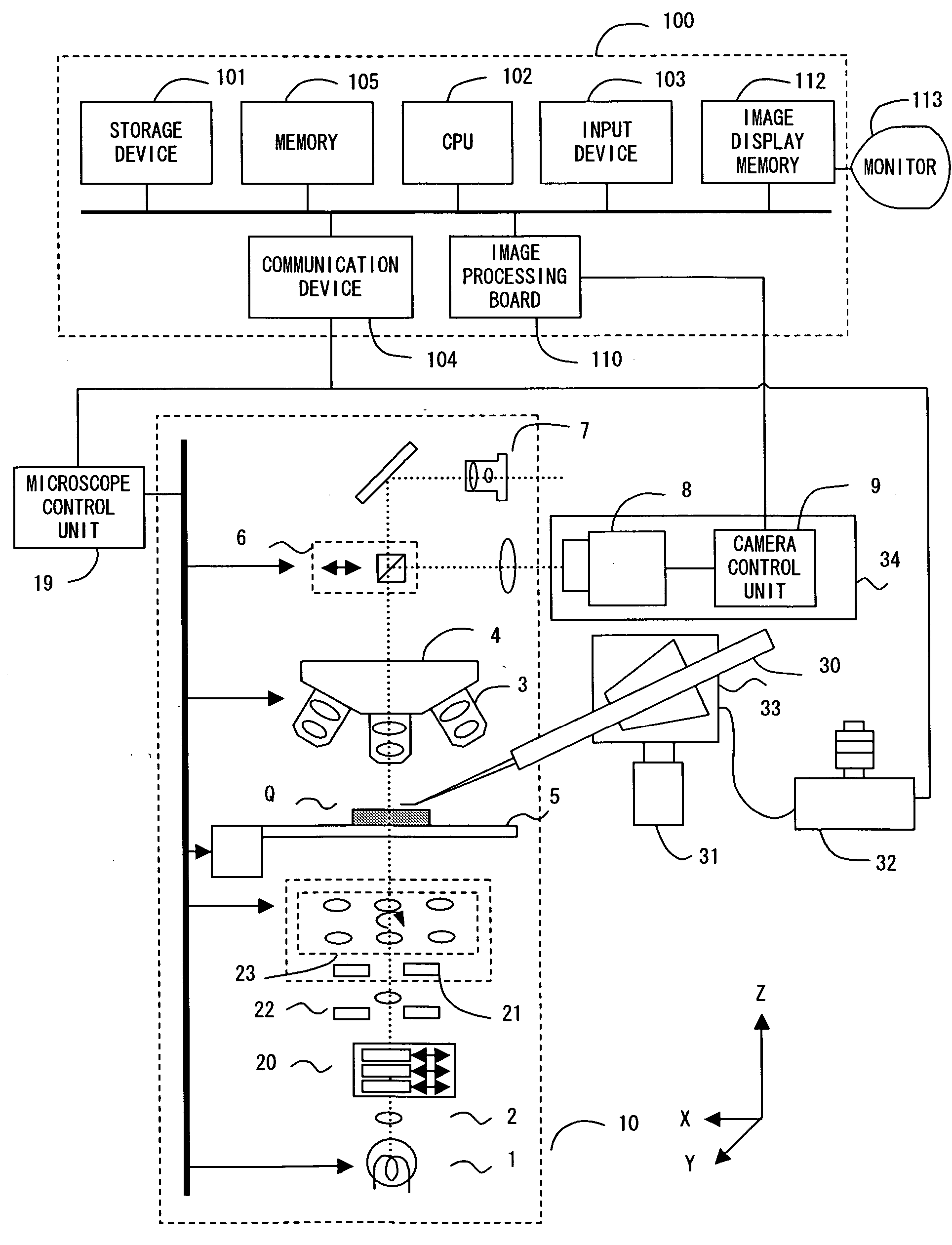
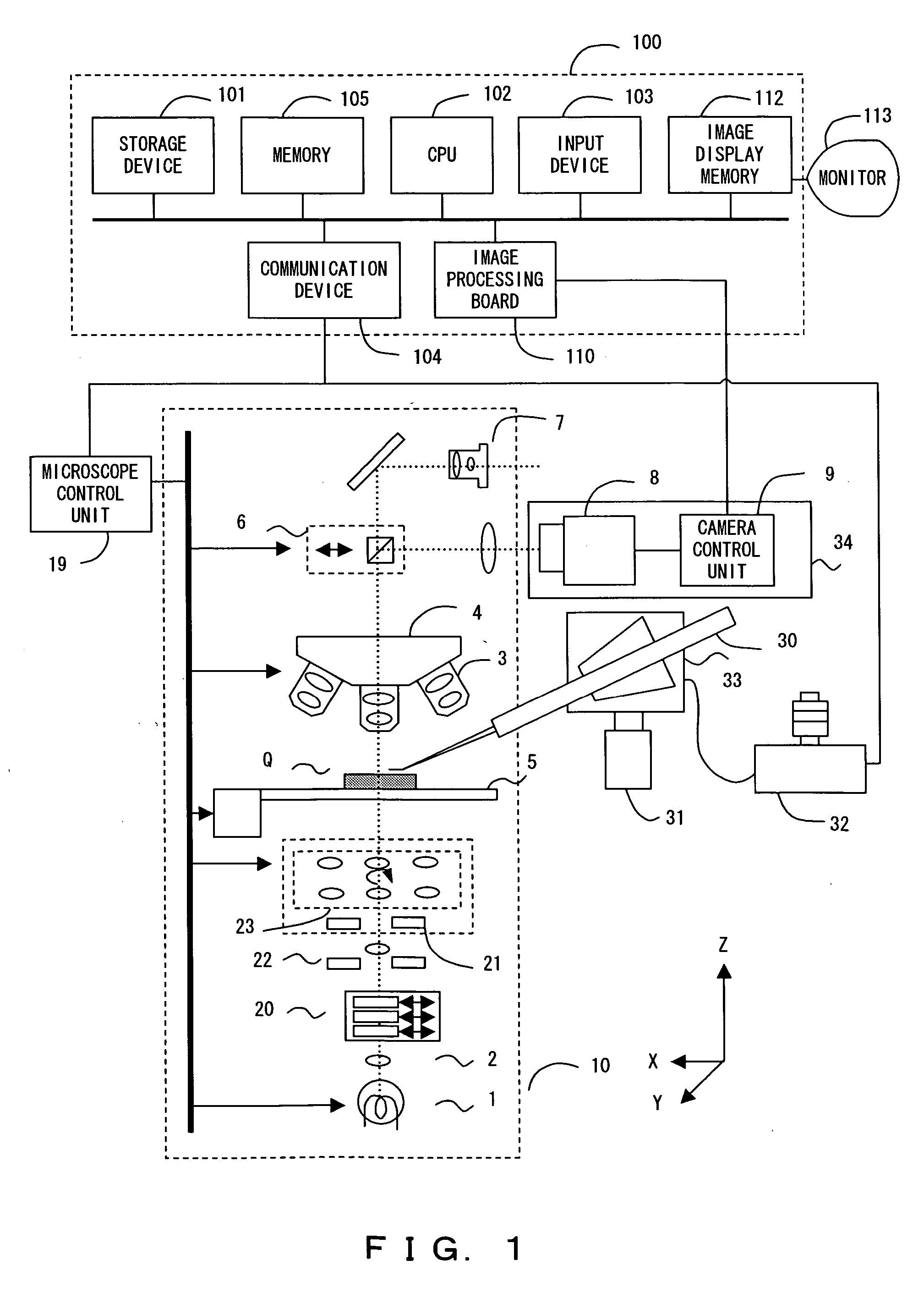
[0041]FIG. 1 shows the entire configuration of the micromanipulation system in this preferred embodiment. This system mainly comprises a microscope unit 10, micromanipulator unit (including 30, 31, 32 and 33), a camera unit 34, a computer 100 and an image monitor 113.

[0042] The microscope unit 10 optically captures a microscopic image from a specimen container Q w...


PUM


Abstract

A micromanipulation system for applying a micro manipulation to an object within the view of a microscope, using a fine needle, comprising: a manipulator driving unit for transferring the fine needle at least along the optic axis direction of the microscope, a micro manipulation starting position determining unit for determining a micro manipulation starting position as a reference position, an object transfer unit for relatively transferring the respective positions of the object and object lens, a focus position detecting unit for detecting a focus position indicating the focus of the object in the object lens, in accordance with the relative transfer of the object, an object transfer control unit for controlling a movement of the object transfer unit, based on the detection result, and a micro manipulation control unit for performing the micro manipulation.

Description

CROSS REFERENCE TO RELATED APPLICATION [0001] This application is based on and claims the benefit of priority of the prior Japanese Patent Application No. 2004-33031 filed in Japan on Feb. 10, 2004, the entire contents of which are incorporated by this reference. FIELD OF THE INVENTION [0002] The present invention relates to a micromanipulation system, and more particularly to a micromanipulation system provided with a microscope and a micromanipulator for operations in minute scales (that is, micro manipulation), such as three-dimensional transfer of a fine needle, injection / absorption and the like within the view of the microscope. DESCRIPTION OF THE RELATED ART [0003] For example, when injecting a DNA solution into a specimen, such as a cell, an egg or the like, a micromanipulation system provided with a micromanipulator and a microscope is used. In the micromanipulator, a fine needle is disposed to inject the DNA solution or the like into the specimen and the microscope is used ...

Claims


Application Information

Patent Timeline
Patent Type & Authority Applications(United States)
IPC IPC(8): G02B21/24G02B21/32G02B21/36
CPCG02B21/244G02B21/36G02B21/32
Inventor YURI, KIYOSHI
Owner OLYMPUS CORP
Why Eureka
Try Eureka