Control unit for optical apparatus and image pickup apparatus
a control unit and optical equipment technology, applied in the field of optical equipment, can solve problems such as changing the shooting angle and the viewfinder's angle of view, and possibly changing the lens position
- Summary
- Abstract
- Description
- Claims
- Application Information
AI Technical Summary
Benefits of technology
Problems solved by technology
Method used
Image

Examples
first embodiment
[0027]FIG. 13 is a perspective view of a lens barrel at a wide angle state, viewed from its front lower left, which lens barrel is provided in a camera according to a first embodiment of the present invention. FIG. 14 is a perspective view of the cam cylinder provided in the lens barrel, viewed from its front lower left.
[0028] A lens barrel 500 in a camera of this embodiment has, as shown in FIG. 13, an outer fixing barrel 555. The outer fixing barrel 555 includes a lens driving motor 506 as a drive source of the lens barrel 500, a motor cover 508, a slip 511, a final gear 512, a potentiometer, a potentiometric gear 514, a pulsed plate, an encoder cover, and a reset photointerrupter 518.
[0029] The lens barrel 500 further includes a cam cylinder 520, a first barrel 524 that holds a first lens unit L1 in an imaging optical system, a second barrel that holds a second lens unit (not shown), a third barrel that holds a third lens unit, and a fourth barrel that holds a fourth lens unit....
second embodiment
[0191] Referring now to FIGS. 11 and 12, a description will be given of a camera according to a second embodiment of the present invention. FIG. 11 shows a sequence to pop up the flash unit by a manipulation of a pop-up button after the power is projected in the camera of the present invention. FIG. 12 is a top view of the camera of the present invention.
[0192] In FIG. 12, 1201 denotes a camera body. 1202 denotes a release button, which starts a shooting preparation in response to the semi-press, and starts a shooting action in response to the full press. 1203 denotes a pop-up button. A manipulation of this button can move or pop up the flash unit that is located at a housed position to the light emitting position.
[0193]1204 denotes a flash unit that irradiates the illumination light onto a subject, and is movable between the accommodation position housed in the camera body 1201 and the light emitting position projecting from the camera body 1201. 1205 denotes a mode dial operated...
third embodiment
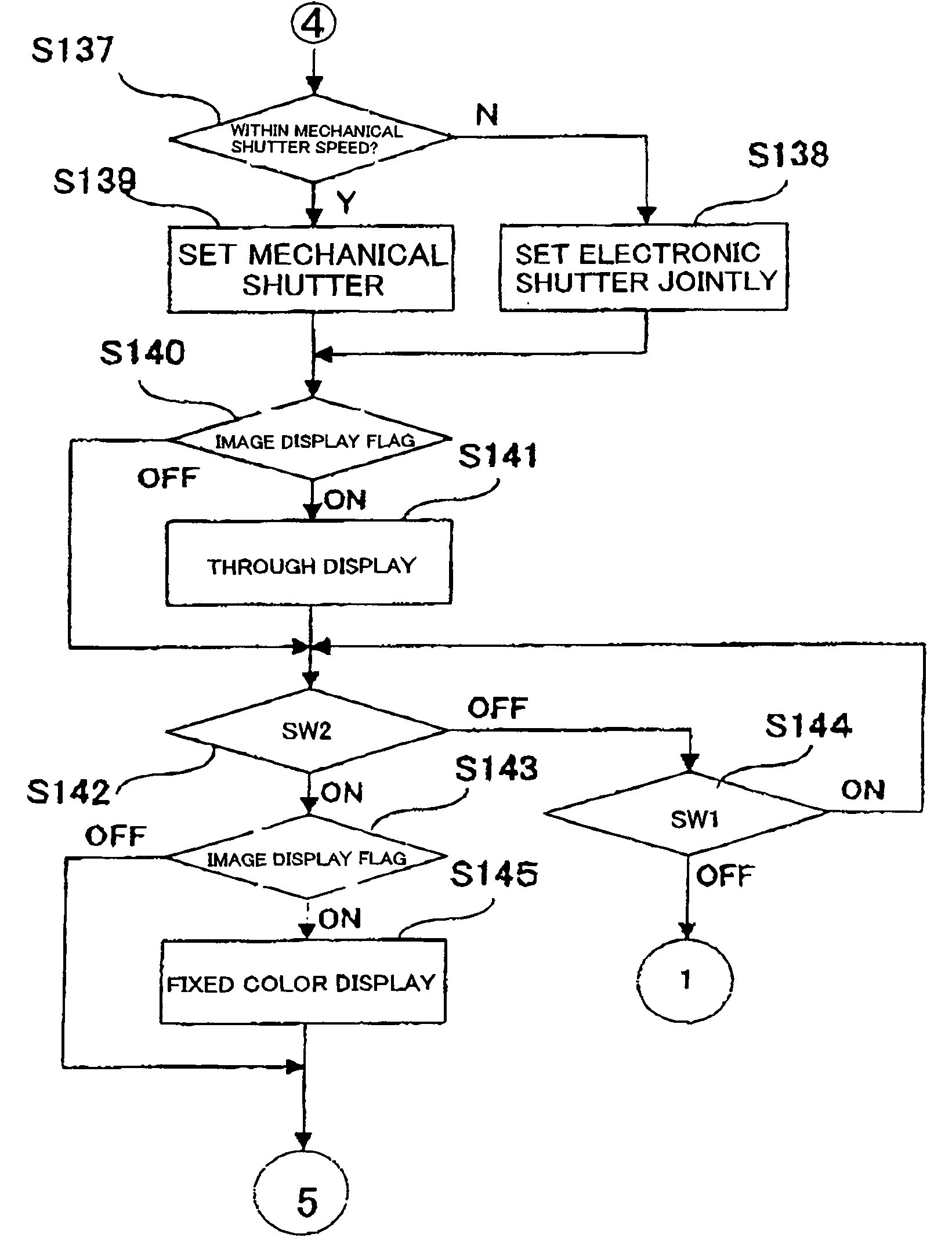
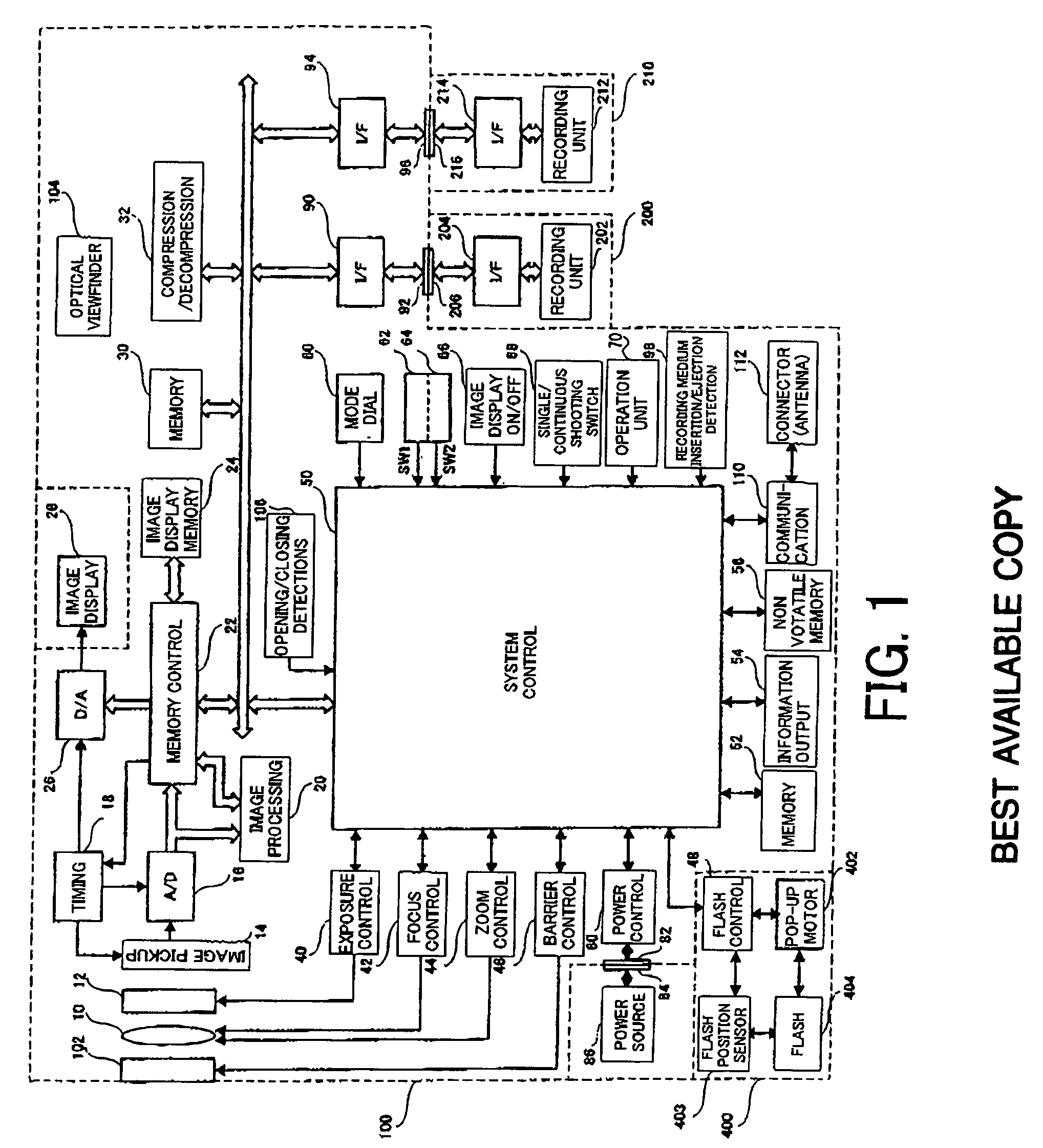
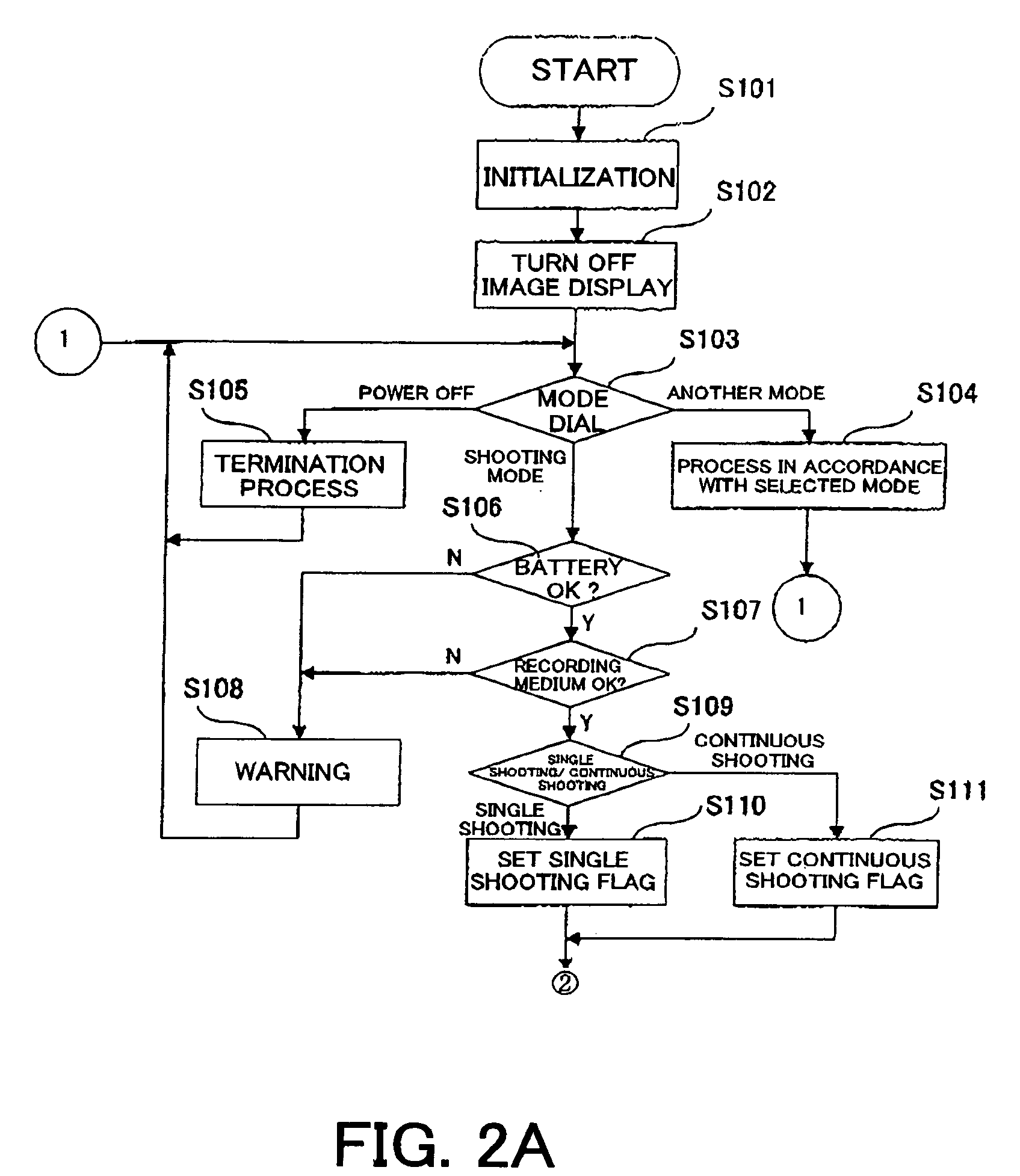
[0207] A description will now be given of an operation of a camera according to a third embodiment of the present invention. In this embodiment, the structure of the camera shown in FIG. 1 and the flowcharts shown In FIGS. 2A, 2B, 4A, 4B 6 to 8 are similar to the first embodiment, and a description thereof will be omitted. Only the different part from the first embodiment will be mainly discussed. Those elements common to the first embodiment are designated by the same reference numerals as those in the first embodiment.
[0208]FIG. 15 shows part of the flowchart of a main routine of the camera according to this embodiment. This flowchart supersedes those in FIGS. 3A and 3B in the first embodiment.
[0209] In a step 531, the system control circuit 50 determines the ON / OFF state of the shutter switch 62 (SW1). When it is in the OFF state, the procedure returns to the step 103 in FIG. 2A. When the shutter switch 62 (SW1) is in the ON state (S531), the system control circuit 50 determine...
PUM
 Abstract
Description
Claims
Application Information
 - R&D
- Intellectual Property
- Life Sciences
- Materials
- Tech Scout
- Unparalleled Data Quality
- Higher Quality Content
- 60% Fewer Hallucinations
Browse by: Latest US Patents, China's latest patents, Technical Efficacy Thesaurus, Application Domain, Technology Topic, Popular Technical Reports.
© 2025 PatSnap. All rights reserved.Legal|Privacy policy|Modern Slavery Act Transparency Statement|Sitemap|About US| Contact US: help@patsnap.com