Head-mounted camera

a camera and head technology, applied in the field of headmounted cameras, can solve the problems of not allowing a user to observe a subject, tiring to observe digital images in a closed space for a long time, and users cannot enjoy themselves/herself, so as to achieve the effect of convenient photo-taking operation

Inactive Publication Date: 2005-08-11
OLYMPUS CORP
View PDF12 Cites 124 Cited by
  • Summary
  • Abstract
  • Description
  • Claims
  • Application Information

AI Technical Summary

Benefits of technology

[0011] Accordingly, it is an object of the present invention to provide a head-mounted camera which allows a user to easily perform a photographing operation without feeling bothered.

Problems solved by technology

Accordingly, when performing photographing at various events, such as sporting events or festivals, the user cannot enjoy himself / herself, unlike when he / she performs a photographing operation while observing actual subjects with his / her eyes.
It has also been found experimentally that it is tiring to observe digital images in a closed space for a long time, unlike when the user observes real subjects with his / her eyes.
However, this does not allow a user to observe a subject and check a photographic range at the same time, and the user has to turn away from the subject to check the image display unit provided for a camera separately provided from the spectacle-type frame.
In the configuration in which an image pickup device is provided on the personal liquid crystal projector, even though a displayed image and a transmitted subject can be viewed at the same time, it is still difficult for a photographer to enjoy himself / herself at an event since he / she has to concentrate on a displayed image during the photographing operation.
Thus, according to the above-described related art, it is difficult for a photographer to behave as naturally as other people during a photographing operation, and he / she feels bothered since his / her actions are restricted by the photographing operation.

Method used


Image

  • Head-mounted camera
  • Head-mounted camera
  • Head-mounted camera

Examples


first embodiment

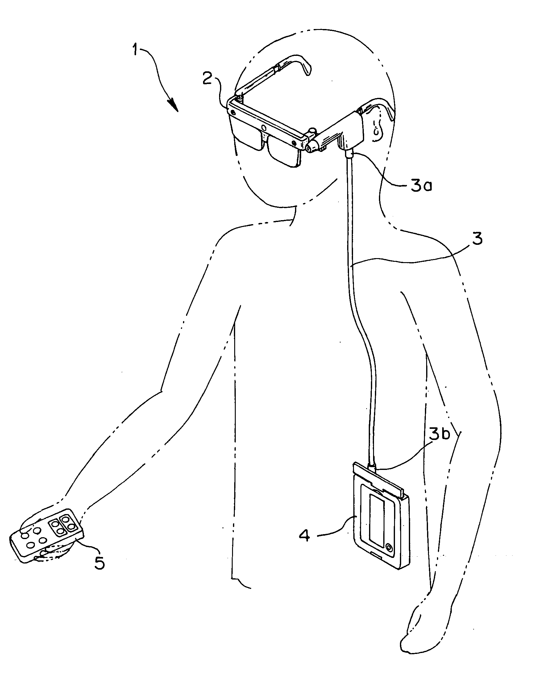
[0070]FIGS. 1 through 46 illustrate a first embodiment of the present invention. FIG. 1 is a perspective view illustrating a state in which a head-mounted camera 1 is used.

[0071] The head-mounted camera (hereinafter simply referred to as the “camera”) 1 includes, as shown in FIG. 1, a head-mounted unit 2 formed substantially in the shape of a pair of spectacles, a controller / recorder 4, which serves as the main body of the camera 1, connected to the head-mounted unit 2 via connecting means, such as a cable 3, and a remote controller 5 for remotely performing input operations for the camera 1.

[0072] The head-mounted unit 2 allows a user to observe a subject substantially directly in a see-through display mode and also to pick up an image of the subject. The head-mounted unit 2 can be worn on the head in a manner similar to ordinary eyesight-correcting spectacles, as is seen from the shape of the head-mounted unit 2. The head-mounted unit 2 is light and small so that the weight and ...

second embodiment

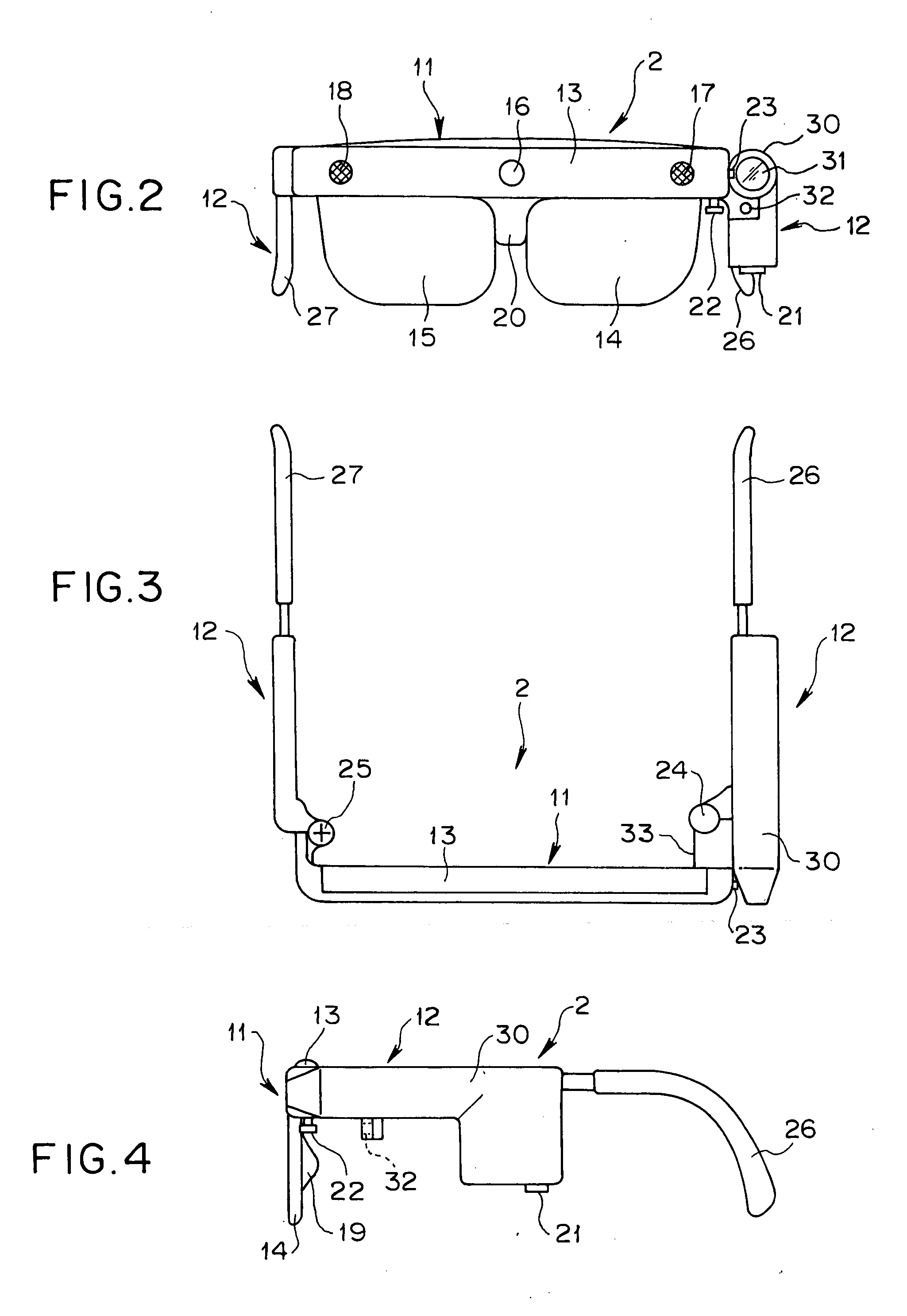
[0300] A second embodiment of the present invention is described below with reference to FIGS. 47 through 50. FIGS. 47, 48, and 49 are a front view, a plan view, and a right side view, respectively, illustrating a head-mounted unit 2A. FIG. 50 is a block diagram illustrating the configuration of an electronic circuit of the camera, mainly the elements different from those shown in FIG. 12.

[0301] In the second embodiment, elements similar to those described in the first embodiment are designated with the same reference numerals, and a detailed explanation is thus omitted.

[0302] In a head-mounted camera, the image pickup device is disposed on each of the left and right temples 12 so that a three-dimensional image observed with the two eyes can be picked up and recorded. In the first embodiment, the first image pickup device 30 is disposed on the left-eye temple 12. In the second embodiment, however, in addition to the first image pickup device 30, a second image pickup device 30R, w...

third embodiment

[0315] A third embodiment of the present invention is described below in detail with reference to FIGS. 51 through 53. FIGS. 51 through 53 are a front view, a plan view, and a right side view, respectively, illustrating a head-mounted unit 2B. In the third embodiment, elements similar to those of the first and second embodiments are designated with the same reference numerals, and an explanation thereof is thus omitted.

[0316] In the head-mounted unit 2B of the camera of the third embodiment, the first image pickup device 30 is divided into a camera portion 30A and a camera circuit 30B, and the camera portion 30A is disposed at, for example, the central portion between the left and right eyes of the frame 13.

[0317] That is, in the upper central portion of the frame 13, elements required for generating an electronic image from an optical image, such as the first photographing optical system 31, the low-pass filter 86, and the CCD 87, are mounted.

[0318] In the left-eye temple 12, th...


PUM


Abstract

A head-mounted camera of the present invention includes the following elements. A first image pickup device includes a first photographing optical system that can change the focal distance and a CCD for converting a subject image formed by the first photographing optical system into an image signal. A see-through image display portion displays a photographic frame indicating the photographic range as a virtual image so that it is superimposed on a subject substantially directly observed by a photographer. A remote controller includes a second operation switch for setting the visual angle of the photographic frame when viewed from the photographer. A controller/recorder includes a first CPU for setting the focal distance of the first photographing optical system so that the visual angle of the photographic frame set by the second operation switch coincides with the field angle of the first image pickup device.

Description

[0001] This application claims benefit of Japanese Application No. 2004-31275 filed in Japan on Feb. 6, 2004, the contents of which are incorporated by this reference. BACKGROUND OF THE INVENTION [0002] 1. Field of the Invention [0003] The present invention relates to head-mounted cameras, and more particularly, to a head-mounted camera which is worn on a head in a manner almost the same as a pair of spectacles. [0004] 2. Description of the Related Art [0005] Hitherto, display devices which are worn on the head to observe images and photographic devices which are worn on the head to perform photographing operations are known. Devices having both a display function and a photographic function are also known. [0006] For example, in the head-mounted display device disclosed in Japanese Unexamined Patent Application Publication No. 7-240889, a user can perform a photographing operation by using a television camera while observing images photographed by the television camera and displaye...

Claims


Application Information

Patent Timeline
Patent Type & Authority Applications(United States)
IPC IPC(8): G02B27/00G02B27/01G02B27/02G02C1/00G02C11/00G03B13/10G03B17/04G03B17/18G03B17/20G03B17/48G03B17/56H04N5/225H04N5/232H04N5/64
CPCG02B27/017H04N5/23293G02B2027/0138G02B2027/014G02B2027/0187G02C11/00G03B13/10G03B13/12G03B13/14G03B13/22G03B17/04G03B17/20G03B17/48G03B2213/02H04N5/2251H04N5/23203H04N5/23245G02B2027/0129H04N23/66H04N23/661H04N23/673H04N23/50H04N23/634H04N23/667H04N23/635
Inventor YAMASAKI, MASAFUMI
Owner OLYMPUS CORP
Why Eureka
Try Eureka